
PIC16C781 For The Air Flow Sensor Circuit

The Air Flow Sensor Circuit utilizes the PIC16C781 microcontroller to effectively measure air flow by leveraging the cooling effect that air exerts on a sensing element. This circuit typically includes a thermistor or a similar temperature-sensitive component that experiences a change in temperature as air flows over it. The cooling effect alters the resistance of the thermistor, which is then converted into a voltage signal by the microcontroller's analog-to-digital converter (ADC).
The circuit may also incorporate additional components such as operational amplifiers to amplify the signal from the thermistor, ensuring that the microcontroller receives a clear and accurate representation of the air flow conditions. The microcontroller processes the voltage signal and can implement algorithms to interpret the data, providing real-time feedback or control outputs based on the air flow measurements.
Power supply considerations are essential for this circuit, as the PIC16C781 typically operates at a voltage range of 2 to 5.5 volts. Proper decoupling capacitors should be included to stabilize the power supply and minimize noise. Furthermore, the circuit may feature communication interfaces such as UART or SPI to send data to external devices or display units for monitoring purposes.
In summary, the Air Flow Sensor Circuit based on the PIC16C781 microcontroller is a sophisticated design that effectively measures air flow by utilizing the cooling effect on a temperature-sensitive element, providing valuable data for various applications, including HVAC systems, environmental monitoring, and industrial processes.The Air Flow Sensor Circuit describes about sensing air flow using micro controller PIC16C781. Air flow is detected by the cooling effect of air .. 🔗 External reference
Related Circuits
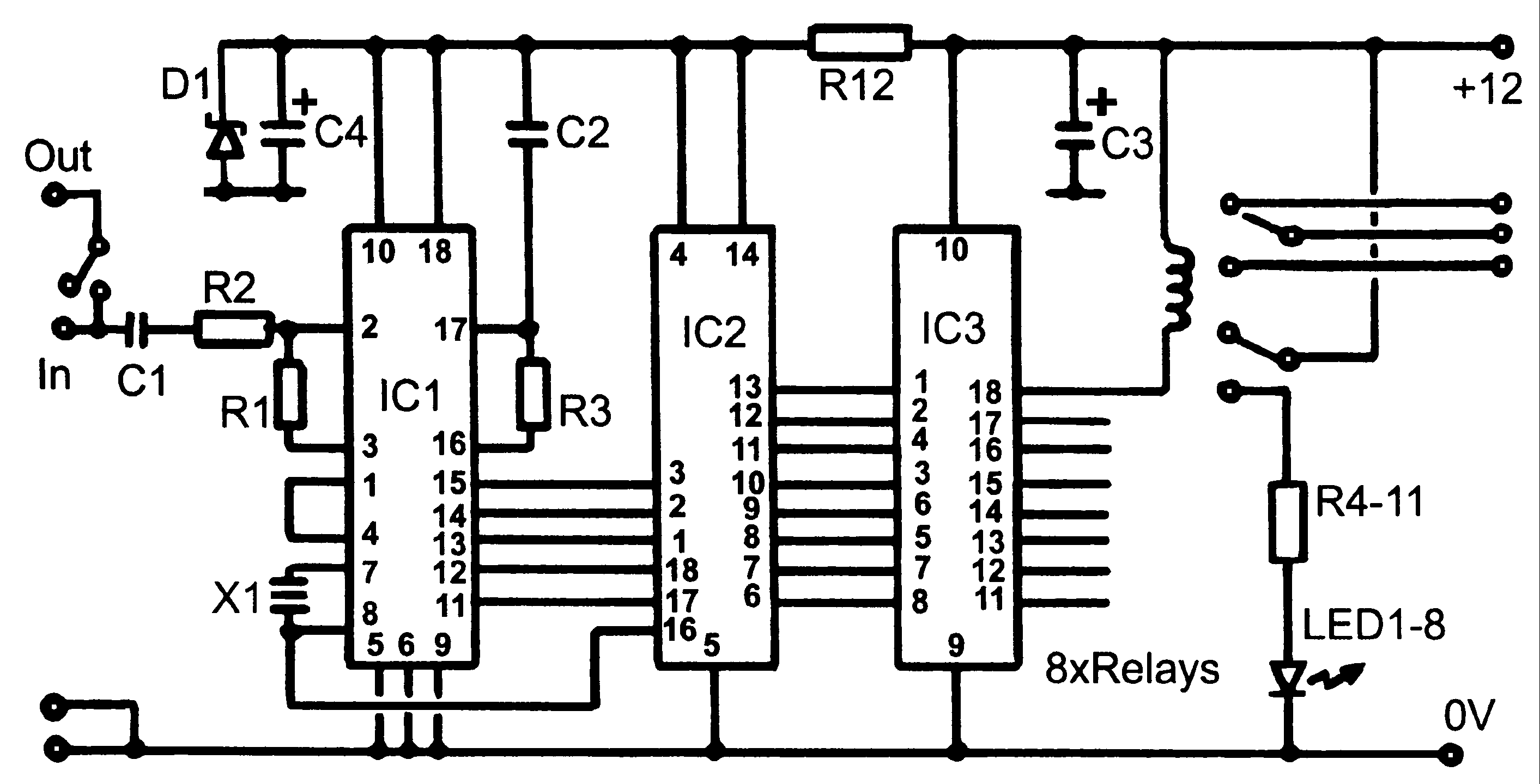
Control monitoring equipment at a TV repeater site is designed to accept commands sent as DTMF tones over the repeater's audio channel. It is capable of switching either AV signals or power supply feeds with currents up to 1...
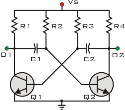
This circuit is designed to drive a relay coil using a low power output, typically from an integrated circuit (IC) such as a 555 timer or a TTL/CMOS device. It facilitates the switching of high loads or loads requiring...
This circuit operates two LED strips in pulsing mode, where one LED strip transitions from an off state to gradually lighting up, then dimming, while the other LED strip performs the opposite action. Each strip can consist of 2...
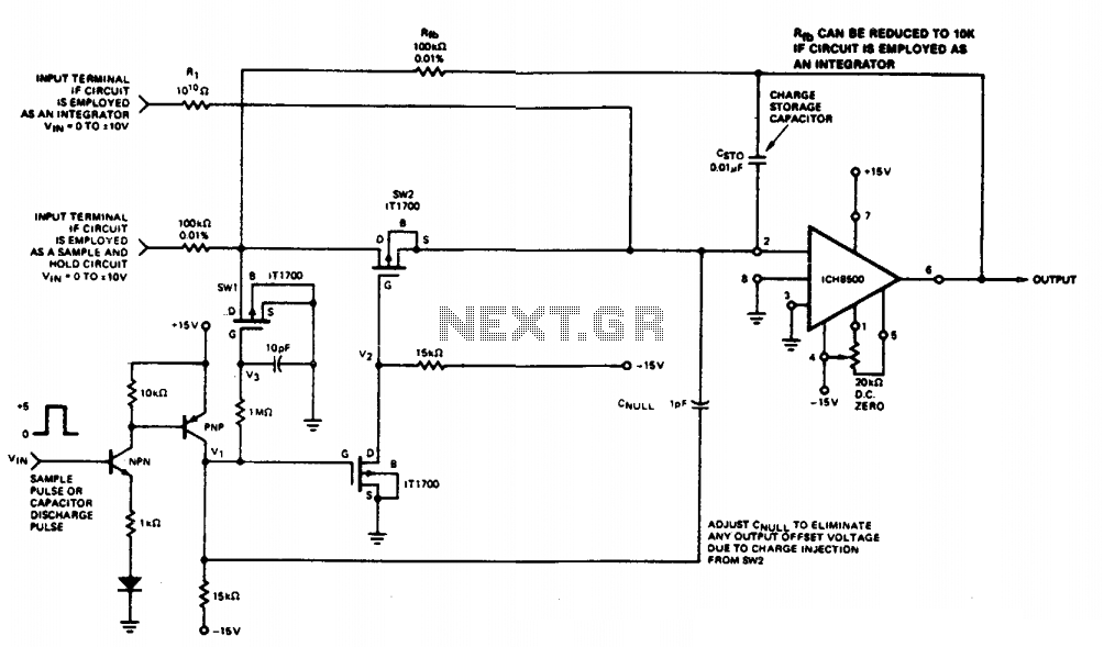
This circuit quickly charges capacitor CST0 to a voltage that matches an input signal. After charging, the input signal is electrically disconnected from the capacitor, allowing the charge to remain on CST0. Since CST0 is part of the negative...
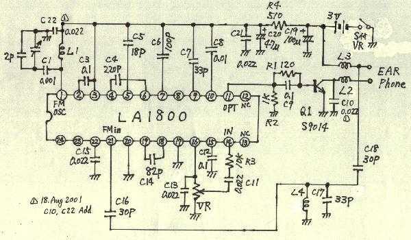
Earphones, batteries are sold separately. AM / FM seems to be a common mold. But stamping is different. AM / FM E193577 UL94V0 board with the AM / FM etching printed circuit board manufacturers are the same. Shape is...
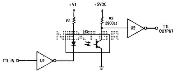
This circuit is a TTL-to-TTL isolator circuit. The driver circuit is an open-collector TTL inverter (U1). When the input is high, the output of the inverter is low. Thus, when the input is high, the output of U1 grounds...