
Temperature Sensor

The AD537 is a precision analog-to-digital converter designed for temperature measurement applications. It employs two reference outputs to facilitate accurate readings. The fixed 1 V reference is essential for establishing a baseline measurement, while the temperature-dependent reference allows for dynamic adjustments based on environmental conditions. Specifically, the temperature reference output varies at a rate of 1 mV per degree Kelvin, enabling the circuit to provide real-time compensation for temperature fluctuations.
At a baseline temperature of 0°C, the circuit's configuration ensures that the 1 V reference, when multiplied by a factor of 0.273, results in a balanced output voltage, effectively calibrating the system to zero. This calibration is crucial for maintaining measurement accuracy and ensuring that subsequent readings reflect true temperature variations.
The circuit operates on a scale of 10 Hz per degree Celsius, indicating that for every degree of temperature change, the output frequency shifts by 10 Hz. This relationship between temperature and frequency allows for straightforward interpretation of the data, with frequency counters being employed as readout devices to display the temperature in real-time.
Power and output signals are transmitted through a two-wire twisted pair configuration, which minimizes electromagnetic interference and enhances signal integrity over longer distances. This design choice is particularly beneficial in industrial environments where noise can significantly impact measurement accuracy.
Overall, the AD537 circuit is a robust solution for temperature measurement, combining precision references, real-time adjustments, and effective data transmission methods to deliver reliable performance in various applications. The AD537 uses its two reference outputs—one fixed at 1 V, the other of which varies with temperature (1 mV per °K). At 0°C, the 1-V reference multiplied by 0.273 will balance this voltage and produce a zero output. The scale in this circuit is 10 Hz/°C, Output from, as well as power to, the circuit, is fed via a two-wire twisted pair. A frequency counter is used as a readout.
Related Circuits

The red wire of the sensor connects to +5 volts, the black wire connects to Ground (GND), and the yellow signal wire connects to analog pin A0 through the same bus as the 10k ohm resistor that is connected...
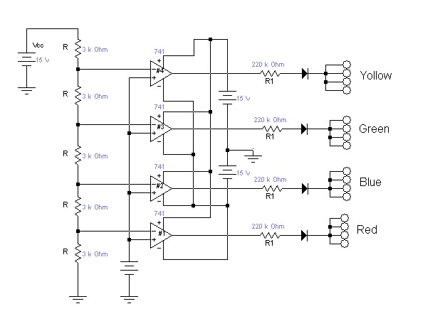
This is a color sensor circuit diagram designed to detect eight colors: green, red, blue, magenta, cyan, yellow, black, and white. It is particularly useful for robotics projects. The object whose color needs to be detected should be placed...
This Project is used to indicate the temperature and it is also used as controller. The system will get the temperature from the IC and it will display the temperature over the seven segment display and this temperature was...
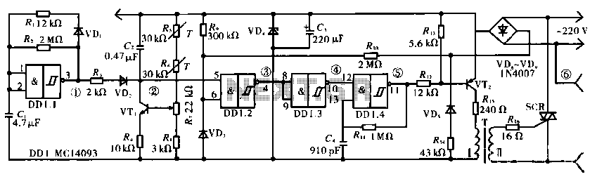
The circuit operates using a temperature stabilizer derived from the main oscillator (DD1.1), along with components including C1, R1, R2, and VD1. It incorporates a monostable multivibrator formed by R3, VD2, VT1, C2, R4, DD1.2, R7, and R8, as...
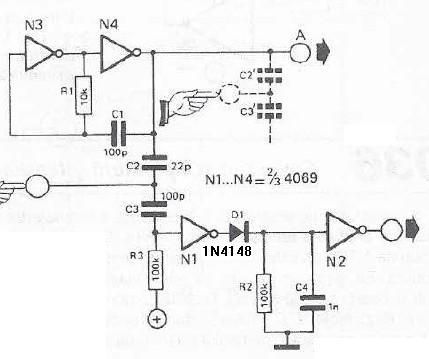
This touch sensor switch is designed using inverters (N1, N2) and several common electronic components. In the standby state, a signal is produced by oscillator N3/N4 at the inputs of N1. When the touch sensor is activated, the hand...
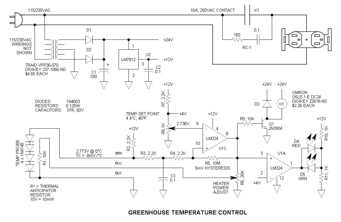
This circuit consists of four 1N4148 diodes connected in series with a thermal anticipation resistor (R1) heat-shrunk together at the end of a three-wire signal cable, which is visible in some photos. The thermal anticipation resistor is an old...