
building rf remote control

The described circuit utilizes an ASK-based RF communication system, operating at a frequency of 433 MHz, which is commonly used for remote control applications due to its balance between range and power consumption. The transmitter module is designed to accept serial data, which can be generated by a microcontroller or an encoder IC. The HT12E encoder IC is responsible for converting parallel data inputs into serial data suitable for RF transmission. This conversion is crucial as it allows for efficient transmission of control signals over the air.
At the receiving end, the HT12D decoder IC plays a vital role in reconstructing the original control signals. It receives the modulated RF signal via the RF receiver module, decodes the serial data back into parallel format, and outputs it to control devices such as motors. The number of bits required for motor control is significant; for a single motor, only two bits are needed for basic on/off control, while controlling two motors requires four bits, allowing for independent control of each motor.
The motor driver circuit is essential for interfacing the low-power signals from the decoder IC with the higher power requirements of the motors. Various options for motor drivers include relays, which can provide isolation and high current handling, and H-Bridge configurations, which allow for bidirectional motor control. Integrated circuits like the L293D and L298 are popular choices for motor control applications, providing built-in protection and simplified interfacing.
In terms of circuit protection, the inclusion of a flyback diode is critical when using inductive loads such as motors. This diode protects the circuit from voltage spikes generated when the motor is switched off. The use of a Darlington pair, such as the ULN2803, can simplify the design by providing both amplification and internal protection, thus enhancing reliability and reducing component count.
Overall, this RF remote control system provides a versatile and effective solution for controlling motors in various applications, from robotics to remote-operated vehicles. The combination of encoder/decoder ICs, RF modules, and motor drivers creates a robust framework for wireless control.The easiest solution would be to take a cheap wireless toy car take out its receiver module along with its remote and use them in your robot. The other way round is this to make your own RF remote We will be using ASK (Amplitude Shift Keying) based Tx/Rx (transmitter/receiver) pair operating at 433 MHz.
The transmitter module accepts serial data a t a maximum of XX baud rate. It can be directly interfaced with a microcontroller or can be used in remote control applications with the help of encoder/decoder ICs. The encoder IC takes in parallel data which is to be transmitted, packages it into serial format and then transmits it with the help of the RF transmitter module.
At the receiver end the decoder IC receives the signal via the RF receiver module, decodes the serial data and reproduces the original data in the parallel format. Now in order to control say a dc motor, we require 2 bits of information (switching it on/off) while we need 4 bits of information to control 2 motors.
HT12E and HT12D are 4 channel encoder/decoder ICs directly compatible with the specified RF module. The schematic is as shown below. In order to drive motors, we would need to connect a suitable motor driver at the output of the decoder IC. The motor driver circuit can consist of a relay, transistorized H-Bridge or motor driver ICs like the L293D, L298 etc.
The example above shows the receiver section using the HT-12D decoder IC for a 4-bit RF remote control system. Similarly the transmitter and receiver module can also use the Holtek 8-bit HT-640/HT-648L remote control encoder/decoder combination for an 8-bit RF remote control system.
Here we have used a flyback protection diode to prevent the damage of the diode. The data output of the decoder ICs should be connected to base of transistor (as shown in the figure). Tip: Also note that we can also use a Darlington pair ULN2803, as it will provide higher voltage and eliminate the need of flyback diode (as it has an internal diode for protection.
🔗 External reference
Related Circuits

The circuit is illustrated. It includes a DC power circuit with a power switch (S3) that converts 220V AC voltage through a buck converter (T), a rectifier (UR), and filter capacitors (C3 and C4) to generate a +9V output....

This device functions as a convenient tool for testing infrared (IR) remote control transmitters used with televisions, VCRs, and similar devices. The IR signals emitted from a remote control are detected by the IR sensor module within the tester,...
The hardware is constructed from two modules, one to capture the signal and provide timing functions, and the second as transmitter placed somewhere near the target equipment. It has been interfaced with an IBM compatible PC on the printer...
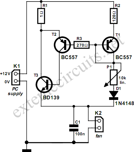
Fans in PCs can be excessively loud. In many instances, the noise generated by the fan can be significantly reduced by decreasing its speed. Although this reduction will lower the cooling capacity, it does not pose a problem as...
THE CUBE is a three-dimensional jigsaw puzzle that features a unique mechanism where a puzzle piece vibrates for approximately one second when it is correctly placed in the puzzle. This functionality is achieved through an electrical design that completes...

The adjustment potentiometer for the Raspberry Pi can modify the conduction angle of the thyristor VI and V2, which in turn adjusts the speed of the DC motor M. The speed feedback circuit is implemented using a tachometer generator...