
KTM03 type for single-phase half-controlled rectifier circuit

The circuit operates by utilizing an adjustment potentiometer connected to the Raspberry Pi, which allows for real-time modifications to the conduction angles of the thyristors VI and V2. This adjustment directly influences the power delivered to the DC motor M, thereby controlling its speed. The thyristors act as electronic switches that can be turned on and off at specific intervals, determined by the conduction angle, which is the duration for which they remain on during each cycle of the AC waveform.
The speed feedback mechanism is critical for maintaining the desired motor speed. It employs a tachometer generator (TG) that produces a voltage proportional to the motor's rotational speed. This voltage serves as feedback to the control system. The feedback signal is then processed through a potentiometer (RP2), which allows for fine adjustments to the feedback level. By tuning RP2, the system can be calibrated to ensure that the feedback is accurate and responsive to changes in motor speed.
This configuration establishes a closed-loop control system, where the actual speed of the motor is continuously monitored and compared to the desired speed set by the user through the potentiometer. If discrepancies arise between the desired and actual speeds, the control system automatically adjusts the conduction angles of the thyristors to correct the motor speed, ensuring stable and efficient operation. The integration of these components results in a robust and adaptable motor control solution suitable for various applications.Adjustment potentiometer RPi, can change the thyristor VI, V2 conduction angle, that is changing the DC motor M speed. Speed feedback circuit is [by tachometer generator TG and potentiometer RP2 (to adjust the amount of feedback)], in fact, is now closed loop control.
Related Circuits
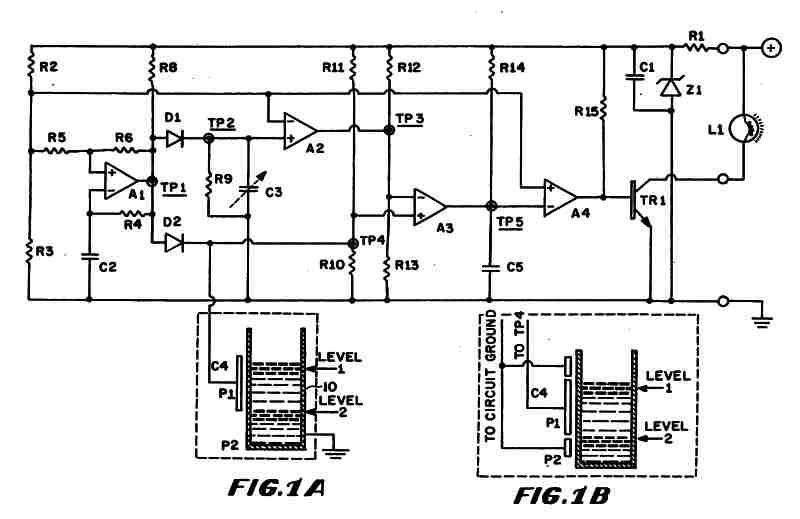
Figure 1 (A) depicts the circuit diagram of one embodiment of the fluid level detector designed. The circuit is typically powered by a 12-volt automobile battery, which is reduced to a 5-volt DC source using a voltage regulator consisting...
This design outlines a simple 1 kHz square wave generator utilizing a few components and the LM3909 integrated circuit, which is beneficial for testing audio equipment. The circuit operates on a single 1.5V battery cell, producing a maximum output...
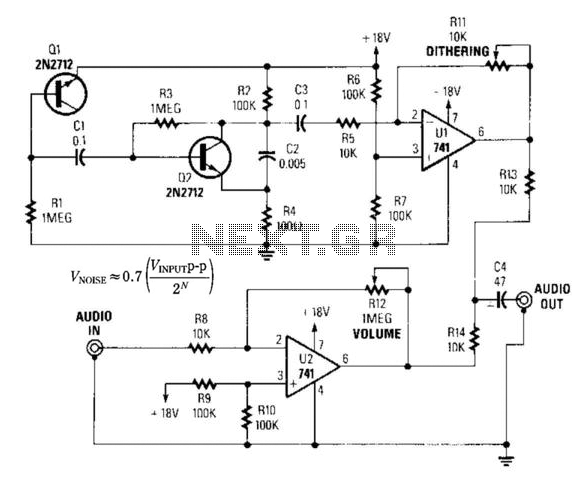
By introducing a small amount of noise to a signal intended for digitization (approximately 0.7 bits), where n represents the number of bits, for instance, an 8-bit signal with a peak-to-peak voltage of 2 V would result in a...
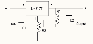
The voltage regulator is an LM317T, and should accept up to about 14 volts without problems. It can handle up to 1 amp, but you WILL need a heatsink on the voltage regulator. I also added DC power jacks...
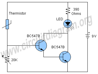
The schematic presented is a project for a simple temperature sensor circuit, also referred to as a heat sensor circuit, which activates an LED in response to heat. The circuit is straightforward to construct and requires only a few...
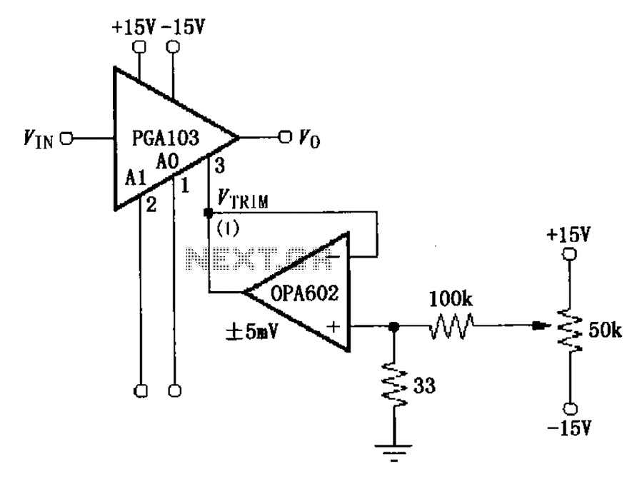
The PGA103 offset voltage correction circuit is designed to minimize the offset voltage for the PGA103 laser correction, ensuring that the gain for three typical offset voltage levels (relative to input) remains below 200 V. Each gain is associated...