burglar alarm using ic timer 555556

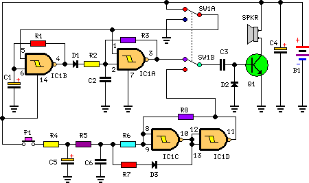
The circuit of a burglar alarm utilizing IC timer 555/556 functions as a security measure to prevent unauthorized entry into a premises. The alarm generates a loud sound when a thin wire connecting resistor R1 with pin 4 of the IC is severed. A thin fiber is employed as the wire, with thinner wires yielding a more responsive alarm. This circuit requires a power supply of 5-15V, and a buzzer is used as the sound output device.
The burglar alarm circuit using the 555/556 timer IC operates in a monostable or astable mode, depending on the configuration. In this setup, the circuit is designed to monitor the integrity of a thin wire, which acts as a security sensor. When the wire is intact, the circuit remains in a low-power state. However, if the wire is cut or broken, the resulting change in resistance at the input pin of the timer IC triggers an output signal.
The circuit typically includes the following components:
1. **IC Timer 555/556**: This is the core component that generates the alarm signal. It can be configured in monostable mode to produce a single pulse or in astable mode for continuous oscillation.
2. **Resistor (R1)**: This resistor is connected to the thin wire and the IC. Its value is chosen to set the sensitivity of the circuit; a lower resistance increases sensitivity.
3. **Thin Wire (Sensor)**: The wire acts as a switch, completing the circuit when intact and breaking the circuit when cut.
4. **Buzzer**: The output device that produces sound when the alarm is triggered. The buzzer can be a piezoelectric or electromagnetic type, depending on the desired sound output.
5. **Power Supply**: The circuit requires a DC power supply ranging from 5V to 15V to operate the timer IC and the buzzer effectively.
The sensitivity of the alarm can be adjusted by changing the thickness of the wire or the resistor value. A thinner wire will break more easily, resulting in a quicker response time for the alarm system. For optimal performance, the circuit should be housed in a secure enclosure to prevent tampering, and the wire should be strategically placed to cover potential entry points.
In conclusion, this burglar alarm circuit is a simple yet effective solution for enhancing home security, utilizing basic electronic components to create an alert system that responds to unauthorized access attempts.circuit of burglar alarm using IC timer 555/556 is functioned as an alarm to prevent thief entering your house. The alarm would produce loud sound when a thin wire connecting resistor R1 with IC pin no 4 is broken.
Thin fiber is used as the wire. The thinner the wire, the more responsive the alarm. This circuit needs 5-15V power supply, bu zzer is used as a speaker. Here is the circuit schematic : 🔗 External reference


