
Battery Charger Display Using LT1639

The Over-the-Top operational amplifier (op-amp) is specifically designed for applications requiring precise current sensing, particularly in battery charger systems. This op-amp configuration allows for accurate monitoring of current flow, which is critical for optimizing charging efficiency and ensuring battery longevity.
In a typical implementation, the op-amp can be connected in a differential configuration to measure the voltage drop across a shunt resistor placed in series with the battery charging circuit. This setup provides a proportional voltage output that corresponds to the current flowing through the shunt resistor. The gain of the op-amp can be adjusted using external resistors to match the desired sensitivity and range of current measurement.
To enhance performance, the op-amp may include features such as low offset voltage, high common-mode rejection ratio (CMRR), and wide bandwidth, which are essential for accurate and stable operation in dynamic charging environments. Additionally, incorporating feedback mechanisms can help maintain linearity and reduce distortion in the output signal.
For practical applications, the op-amp circuit may be integrated with a microcontroller or analog-to-digital converter (ADC) to facilitate real-time monitoring and control of the charging process. This integration enables the implementation of sophisticated charging algorithms that can adapt to varying battery conditions, ensuring optimal charging profiles and enhancing overall system efficiency.
In summary, the Over-the-Top operational amplifier serves as a vital component in battery charger designs, providing accurate current sensing capabilities that are essential for effective battery management.The Over-the-Top type of operational amplifier is ideal for use as a current sense for battery charger applications. The design described here can be used.. 🔗 External reference
Related Circuits
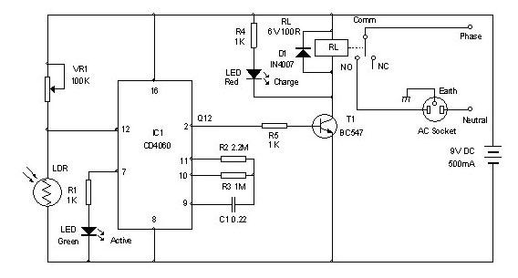
Timer for Charger Circuit Diagram. This timer circuit assists in maintaining the battery in optimal condition by enabling automatic charging for 5 to 6 hours daily, allowing the device to be left unattended. The timer circuit for the charger is...
This circuit is a small digital roulette. It consists of an oscillator IC1, a counter IC2, and transistors Q1-7 that drive the common cathode display DSP1. The power supply typically comes from a 9V battery, but it can also...
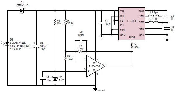
A simple supercapacitor charger electronic project can be designed using the LTC3625 integrated circuit (IC) from Linear Technology. This circuit is capable of charging two supercapacitors in series to a fixed output voltage of either 4.8V/5.3V or 4V/4.5V, which...
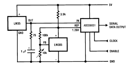
The circuit illustrates a Temperature to Digital Converter diagram utilizing the LM35 sensor, which includes a beneficial bypass capacitor connected from VIN to ground and a series RC damper. The described circuit employs the LM35 temperature sensor, a precision integrated...
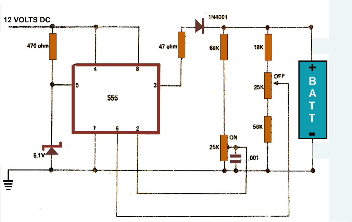
The simple battery charger circuit design presented here utilizes the versatile IC 555 as its primary component. This circuit is capable of charging various types of rechargeable batteries within the specified limits outlined in the article. The battery charger circuit...
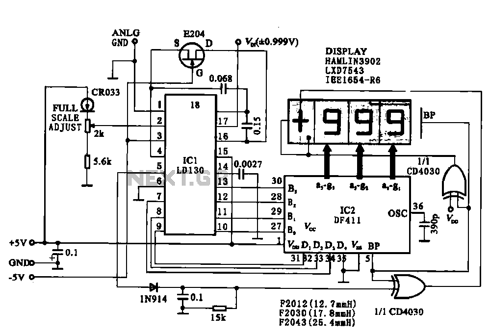
This circuit illustrates a display driving system for a digital voltmeter. The liquid crystal display (LCD) does not emit light by itself; it relies on external incident light for visibility. The integrated circuit (IC) LD130 serves as an input...