
By a clock with a calendar Ultrasonic Ranging IC SB5027 a circuit diagram of an ultrasonic range finder

The ultrasonic range finder circuit utilizes the Ultrasonic Ranging IC SB5027, which is designed to measure distances by emitting ultrasonic waves and calculating the time taken for the waves to return after reflecting off an object. This IC integrates various functionalities, including a clock with a calendar, which can be employed to timestamp measurements or synchronize operations.
The circuit typically includes a transmitter and receiver pair, where the transmitter emits ultrasonic pulses at a specific frequency. The SB5027 manages the timing of these emissions and listens for the echoes. Upon receiving the reflected signal, the IC calculates the distance based on the speed of sound in air, utilizing the time delay between emission and reception.
Additional components in the circuit may include a microcontroller for processing the distance data, a display module for visual output, and various passive components such as resistors and capacitors to ensure stable operation. The microcontroller can be programmed to trigger measurements at regular intervals, utilizing the calendar feature to log data over time, which can be useful for applications requiring historical distance tracking.
Power supply considerations are also critical in the design, as the circuit should operate efficiently within the specified voltage range of the SB5027. The layout should minimize interference and optimize the positioning of the transmitter and receiver for accurate measurements. Overall, this ultrasonic range finder circuit is a versatile tool for various applications, including automation, robotics, and obstacle detection. By a clock with a calendar Ultrasonic Ranging IC SB5027 constitute a circuit diagram of an ultrasonic range finder
Related Circuits
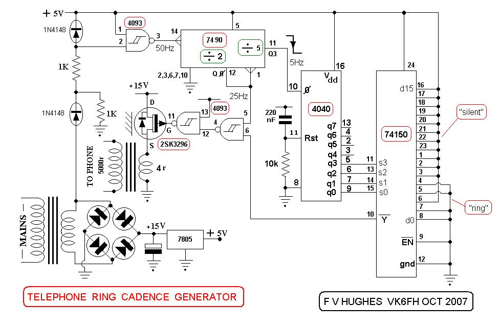
This design aims to restore the classic style of telephones that utilized a pair of gongs to signal an incoming call, evoking a sense of nostalgia with the familiar sound of ringing bells. Presented here is a "Telephone Ring...
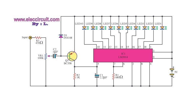
This is a simple light-running circuit synchronized with music. The circuit is straightforward, operating in mono, and requires only a few components. It can be connected to the output of a CD player. The described circuit utilizes a basic audio...
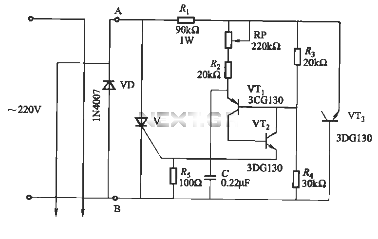
This circuit utilizes an "and other potential triggers" circuit. The term equipotential trigger refers to a crystal bidirectional thyristor trigger, which can be activated by either a positive or negative trigger. In this setup, the control electrode G and...

A TDA1024 electronic thermostat measures soil temperature using thermistor R6. The circuit employs zero-crossing switching to control the heater, which is constructed from elastic-coated steel wire. A potentiometer (PI) is utilized to adjust the temperature setting. The heater must...
The Lorenz system is one of the few standard oscillators commonly used to explore chaos. An accessible description of its mathematical features and chaotic dynamics is presented by Thompson and Stewart. This important system was originally developed as a...
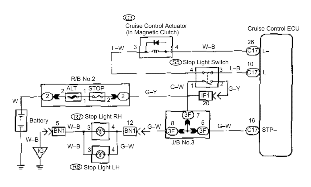
When the brake pedal is depressed, battery positive voltage normally applies through the STOP fuse and stop light switch to terminal STP of the ECU, and the ECU turns the cruise control off. A failsafe function is provided so...