
Circuit Implementation of a Chaotic Lorenz System

The Lorenz oscillator is a significant example of chaotic systems in electronic circuits, characterized by its three-dimensional phase space defined by the states X, Y, and Z. The parameters s, R, and b influence the behavior of the system and are critical in achieving chaotic dynamics. The scaling of the system equations allows the representation of these states within a practical voltage range suitable for electronic components.
The choice of ±10 V signals is particularly relevant for ensuring that the circuit operates effectively within the limits of standard operational amplifiers and multipliers. The use of AD633 multipliers facilitates the necessary mathematical operations required by the Lorenz equations, while TL082 operational amplifiers provide the necessary gain and buffering for the circuit.
The circuit's design also emphasizes the importance of maintaining stability and precision in the face of component tolerances. The implementation of a Zener diode for voltage reference ensures that the circuit remains robust against variations in supply voltage, which is crucial for replicating the chaotic behavior of the Lorenz attractor.
The ability to adjust the parameters R, s, and b dynamically through variable resistors allows for real-time experimentation with the circuit, enabling the exploration of bifurcation phenomena and other chaotic behaviors. The careful selection of component values, such as using a potentiometer for RR, enables the tuning of the circuit to achieve the desired chaotic output effectively.
In summary, the electronic realization of the Lorenz oscillator serves as a profound demonstration of chaos theory in action, providing valuable insights into the behavior of nonlinear dynamical systems through its implementation in analog electronics.The Lorenz system is one of a few standard oscillators commonly used to explore chaos [1]. An accessible description of its mathematical features and chaotic dynamics is presented by Thompson and Stewart [2]. This important system was originally developed as a simplified mathematical model of atmospheric instabilities and does not derive from a ba
sic circuit topology. As such, realizing an electronic Lorenz oscillator requires an explicit analog computer implementation of the oscillator equations. A few designs for realizing a Lorenz attractor have been published in the literature [3 ‘14]. Here, we present an original circuit design that is derived directly from the Lorenz system equations.
where X, Y, and Z are the states of the system and s, R, and b are parameters. Typical parameter values that yields chaotic dynamics are s=10, R=30, and b=8/3. For these values, the attractor generated by numerically integrating (1) is shown in Figure1. Typical waveforms for the three dynamical states are shown in Figure2. To obtain a practical circuit design for the Lorenz system, it is necessary to scale the system equations. To this end, we define the new system states For a practical circuit, it is desirable to use ±10 ‘V signals to represent the system states.
Based on the magnitude of the oscillations shown in Figure1, choosing a=1/3 yields states that map directly to the desired voltage range. As such, the scaled system is Figure3. Numerical Lorenz attractor for the scaled system with a=1/3. A circuit schematic that closely realizes the scaled Lorenz system is shown in Figure4. The voltages at the nodes labeled x, y, and z correspond to the states of the scaled system (4). The multipliers are each AD633, for which the additional summing node is grounded. The operational amplifiers are all TL082 or equivalent. The circuit is powered with ±15V. Since the input to the AD633 is very high impedance, the three-volt reference for Va can be implemented using resistors as a voltage divider; however, it is preferable to use a Zener diode or other fixed voltage reference to make the circuit independent to changes in the supply voltages.
As drawn, the circuit oscillates near 2kHz; however, to vary the frequency without affecting the chaotic nature, all three capacitors may be scaled equally. The oscillator parameters R, s, and b for the Lorenz circuit are controlled with three circuit resistors.
The R parameter is set with the variable resistor RR by the relation Often for bifurcation studies of the Lorenz system dynamics, the parameter R is varied while s and b are held fixed; as such, RR is implemented here using a variable resistor. Clearly, variable resistors can also be used for Rs and Rb if one desires to adjust these parameters while the circuit is running.
The scale parameter a is set with the reference voltage Va using As drawn in Figure4, the circuit is configured for s=10, b=8/3, a=1/3, and a variableR. Using a 10kW potentiometer for RR yields the range 3‰¤R<, and setting RR~1kW provides a chaotic output with R~30. An attractor measured from the circuit with these parameters is shown in Figure5. Corresponding typical captured waveforms are shown in Figure6. Figure6. Typical waveforms measured from Lorenz circuit. . Technically, this symmetry makes the system structurally unstable. That is, arbitrarily small deviations in the mathematical description of the oscillator will destroy this symmetry and result in a qualitatively different system.
In terms of a physical circuit, this is bad news, since an exact realization of the equations is impossible due to limited precision of the circuit components. As a result, a Lorethis figure, the dynamics of the Lorenz system is well modeled by a unimodal, one-dimensional return map [15].
Such a simplification is important, especially in the application of symbolic dynamics to this system. 🔗 External reference
Related Circuits
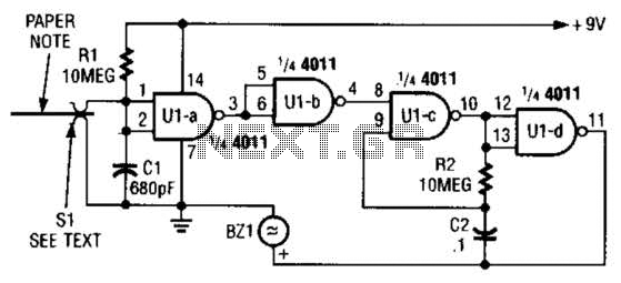
This device prevents paper notes and memos from being overlooked. A paper note placed between two fingers made of a conducting material (metal or conductive plastic) breaks the circuit, allowing pair 1 of Ul-a to go high. This causes...
The Electronic Cash Register (ECR) keeps track of sales transactions quickly and effectively. An abundance of PLUs (Price Look Ups) and department keys accommodate a variety of merchandise items. This means a faster, more accurate check out process and...
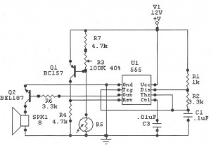
The following circuit illustrates a Sun Up Alarm Light Alarm Circuit Diagram. This circuit is based on the 555 Integrated Circuit (IC). Features include simplicity and cost-effectiveness. The Sun Up Alarm Light Alarm Circuit employs the 555 timer IC in...
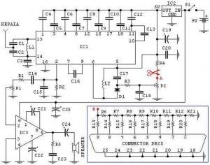
This is an FM radio receiver circuit that can be used with a PC. The circuit includes several regulations: A) The P1 potentiometer is used to adjust the sound intensity. B) The P2 potentiometer is used to adjust the...

The circuit is a high-power car audio amplifier schematic. It functions as a car audio amplifier using the PA02 and LH0101 integrated circuits (ICs). Each IC delivers an output power of 30W with an 8-ohm impedance. The part list...
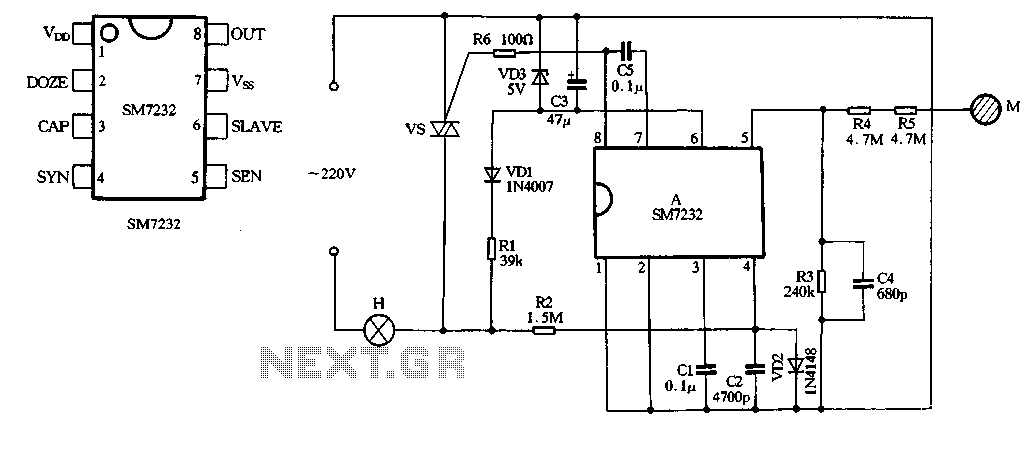
The core component of the circuit is the dimmer, utilizing the SM7232 integrated circuit. The pin configuration includes: 1) VDD, the positive power supply terminal; 2) DOZE; 3) CAP; 4) SYN, which synchronizes input power frequency using an internal...