
C64 S-video mod

This modification enhances the versatility of the Commodore 64 (C64) by allowing users to connect to modern display devices that support S-video input. The S-video connection provides improved video quality compared to the traditional composite video output. By replacing the original audio/video connector with a standard S-video connector, users can achieve a clearer and more defined image on compatible displays.
The RF modulator RCA jack serves as the audio output in this setup. This allows the C64 to transmit audio signals through a familiar and widely used connector, facilitating compatibility with various audio equipment, such as speakers or home theater systems. The modification not only improves the quality of the video signal but also ensures that audio can be output through a standard RCA connection, which is prevalent in many audio systems.
To implement this modification, it is essential to carefully desolder the existing audio/video connector from the C64 motherboard. The new S-video connector should be soldered in place, ensuring that the connections are secure and properly aligned. Additionally, the RF modulator RCA jack must be verified for functionality, as it will now be responsible for carrying the audio signal.
This modification is particularly beneficial for users who wish to connect their C64 to modern televisions or monitors that lack composite video inputs. By utilizing standard connectors, the modification not only simplifies the connection process but also enhances the overall user experience with the C64.Here`s one simple mod swap the C64 audio/video connector to something that can take a regular s-video cable and use the RF modulator RCA jack for audio out. Standardish connectors just save from that much hassle. 🔗 External reference
Related Circuits

The LV2283VB is an FM Transmitter Integrated Circuit (IC). The multiplex (MPX) block generates a stereo modulated composite signal from left and right audio inputs. The RF Voltage-Controlled Oscillator (VCO) incorporates the FM modulation function. The Phase-Locked Loop (PLL)...

The integrated circuit (IC) is a multistandard vision and sound intermediate frequency (IF) phase-locked loop (PLL) demodulator that operates without the need for alignment. It supports multiple standards, including PAL, SECAM, and NTSC, and is capable of processing both...
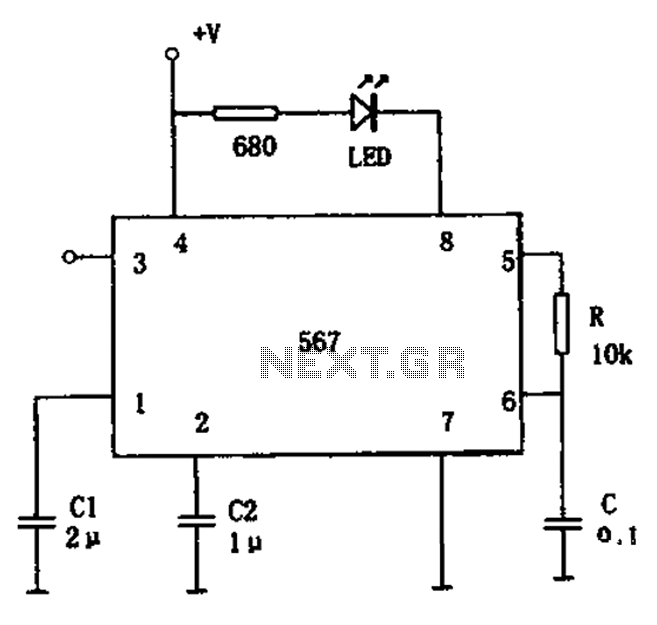
The FM demodulation circuit is illustrated in Figure 567. The FM signal is input at pin 3, and the demodulated signal is output from pin 5. The center frequency of the FM demodulation circuit is determined by the formula...
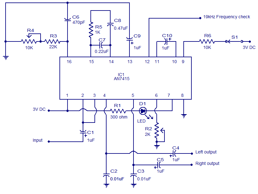
This weblog focuses on electronic circuit schematics, PCB design, DIY kits, and electronic project diagrams. The circuit presented is a stereo FM PLL demodulator based on the AN7415. C1 serves as the input coupling capacitor, blocking any DC voltage...
Designing various electronic circuit systems (synthesizer, modem, decoder, data converter, etc.) often requires a frequency modulator subsystem. An FM modulator is a crucial component in these systems. An FM modulator is an electronic device that encodes information in a carrier...
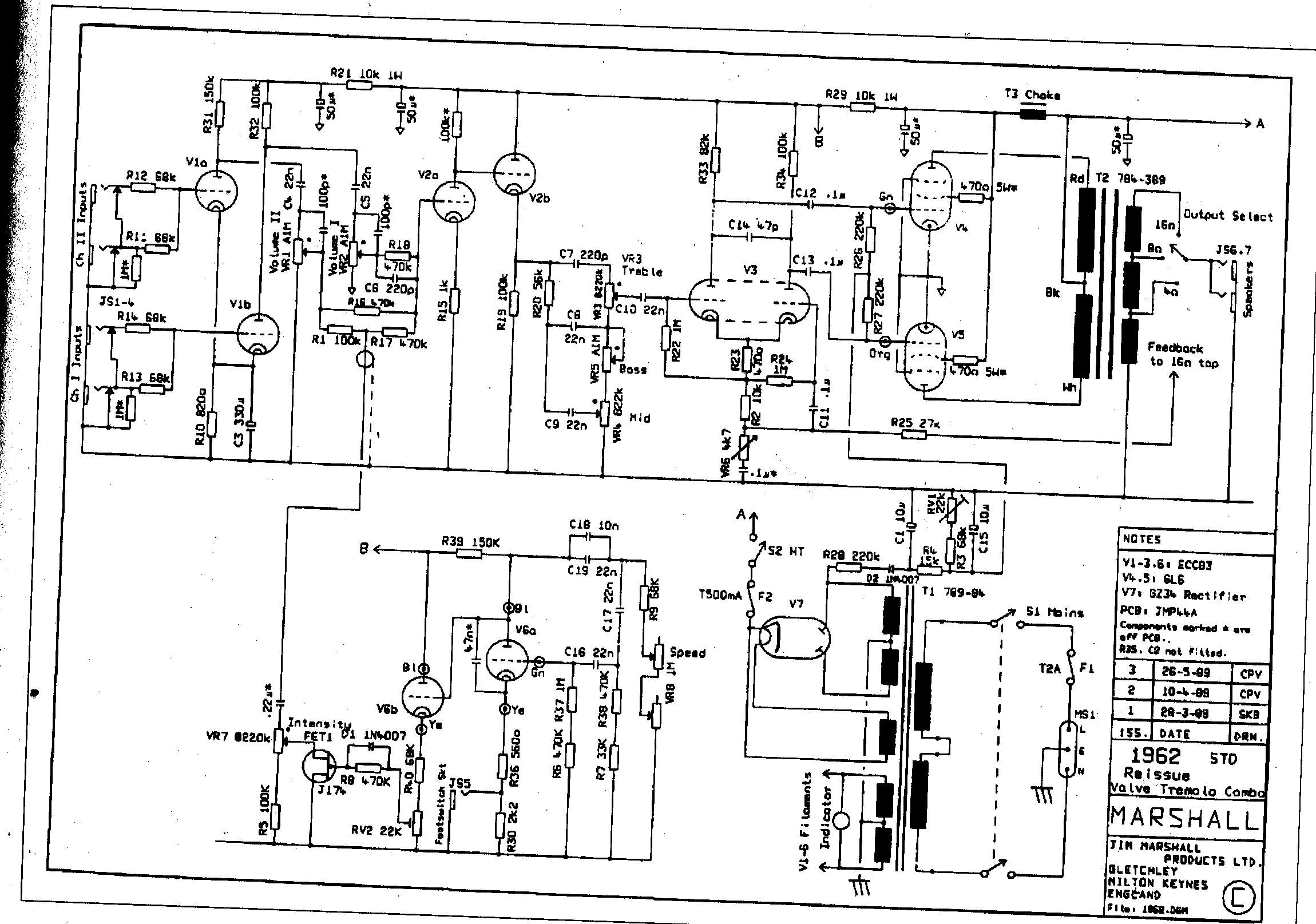
The Sovtek 5881 tubes included in these amplifiers are low-quality and produce a corresponding sound. It is advisable to replace all tubes with a Sovtek GZ34, Valve Art or GT KT66 tubes, and Ei Gold preamp tubes. The KT66...