
TDA9887 IF-PLL demodulator with FM radio circuit

The IC's design allows it to handle a variety of modulation schemes, making it suitable for diverse applications in television and radio broadcasting. The PLL architecture ensures that the demodulation process is stable and accurate, providing high-quality audio and video output. The inclusion of both AM and FM processing capabilities allows the IC to be utilized in a wide range of devices, from traditional television sets to modern multimedia receivers.
The device's multistandard functionality is particularly beneficial in regions where different broadcasting standards coexist, enabling seamless reception and playback of various signal formats. The alignment-free operation simplifies the manufacturing process, reducing production costs and improving reliability. Additionally, the IC's capability to demodulate FM radio signals at 10.7 MHz makes it an ideal choice for integration into FM radio receivers, ensuring clear and precise audio reproduction.
In summary, this IC serves as a versatile solution for demodulating both vision and sound signals across multiple standards, making it a valuable component in the design of modern electronic communication devices. Its advanced features and robust performance characteristics position it as a critical element in the field of audio and video processing.The IC is an alignment-free multistandard (PAL, SECAM and NTSC) vision and sound IF signal PLL demodulator for positive and negative modulation, including sound AM and FM processing. A special function is implemented for the demodulation of FM radio signals (fRIF = 10. 7 MHz). 🔗 External reference
Related Circuits

The purpose of this circuit is to maintain a permanent magnet DC motor at a constant speed, which is set externally. This is achieved by monitoring the current flowing through and the voltage across the motor's brushes. The schematic for...
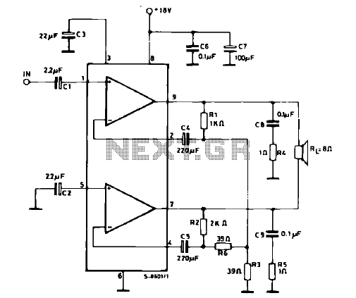
The schematic illustrates a 12 W Bridge Amplifier circuit diagram utilizing the TDA2007A, a class AB dual audio power amplifier. This amplifier is specifically designed for stereo applications in music centers, television receivers, and portable radios. As stated in...
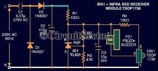
This document presents an infrared remote control tester circuit that can be constructed at a low cost. The circuit is built around the infrared receiver module TSOP1738. The state of the remote control can be observed through the sound...
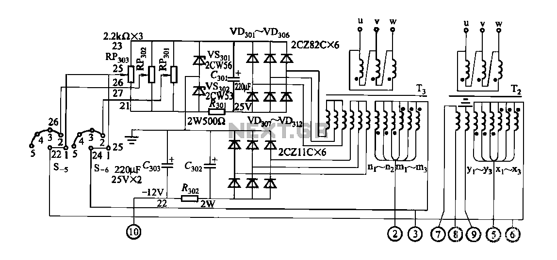
FGDF-3 is a three-phase low-temperature iron plating power supply circuit, while the KGDF-3 is a single-phase low-temperature iron plating power supply device that encompasses all the characteristics of the power supply unit. This design allows for an even distribution...
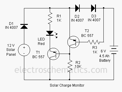
This add-on circuit can be attached to the solar charger to indicate whether the battery is charging. It lights a red LED to signal that the battery is charging. The described add-on circuit serves as a visual indicator for the...
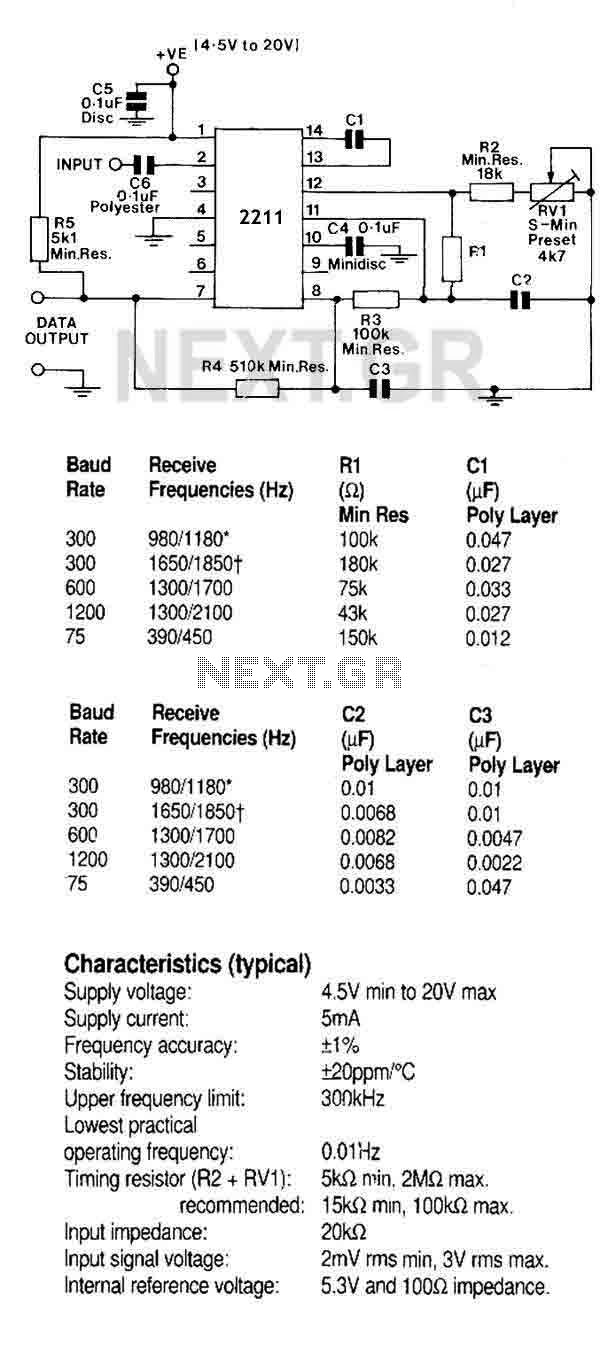
A monolithic phase locked loop for data communications. The IC contains a basic phase locked loop for tracking an input signal within the pass band, a quadrature phase detector which provided carrier detector and an FSK voltage comparator which...