
Cable Tester Circuit

The cable tester circuit is designed for efficient and reliable testing of cable integrity. The two op-amps configured as window comparators are set up to monitor the voltage levels across the cable conductors. When a short circuit occurs, the voltage level drops below a predefined threshold, triggering the red LED to illuminate, signaling the presence of a fault. Conversely, if an open circuit is detected, the voltage remains above the threshold, and the yellow LED is activated to indicate an open conductor.
The third op-amp comparator plays a crucial role in verifying the integrity of the circuit. It ensures that when all conductors are intact, the green LED lights up, providing a clear visual indication that the cable is functioning as intended.
The inclusion of a bar-graph display enhances the usability of the tester by allowing for real-time monitoring of each conductor's status. Each LED in the bar-graph corresponds to a specific conductor, illuminating sequentially as the tester cycles through the conductors. This feature not only facilitates quick identification of faults but also provides a comprehensive overview of the cable's condition.
Overall, the design of this cable tester emphasizes clarity and functionality, utilizing simple yet effective components to deliver accurate testing results. The use of color-coded LEDs and a bar-graph display ensures that users can easily interpret the status of the cable under test, making it an invaluable tool for technicians and engineers in the field of electronics. At the heart of the cable tester are two op amps, which are used as a window- comparator to indicate a short- or open-circuit condition. A third op-amp comparator is used to indicate a good circuit (i.e., neither open nor shorted). Colored LEDs are used to show the condition of individual conductors within the cable under test; a red one to indicate a short between conductors, a yellow one to identify an open conductor, and a green one to signify that the conductor is okay.
Individual LEDs of a bar-graph display are used to show which conductor in the cable is being tested.
Related Circuits
This circuit is designed to test the servo motor of a parabolic antenna. It functions effectively, although a system with a low-noise block feed (LNBF) is generally more suitable. Many users continue to utilize systems that employ an LNB...
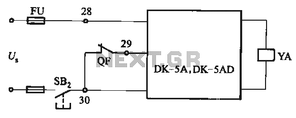
The DK-5A and DK-5AD AC power control circuit is illustrated in Figure 6-77. The figure includes a closing button (SBz) and a line (YA) connected to the closing electromagnet coil (U). This circuit is designed for the operation of...
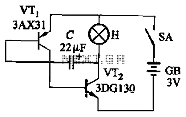
The circuit depicted in Figure 13-4 utilizes triode control. Two transistors, VTi and VTz, are coupled via a capacitor (C) to alternately turn on and off, producing a flashing light effect. The flash frequency is influenced by the capacitance...
The safe 12V car adapter described here can be used to limit the current from a +12 volt car battery, available from the in-dash cigar lighter power port, to below 2.6A. The 12V car adapter is designed to ensure that...
Meteoplug is a client-server application. The client application requires minimal storage and computing power, enabling it to be embedded in small devices with low power demands, typically around 1 watt (or 1-2 watts depending on power supply efficiency). These...
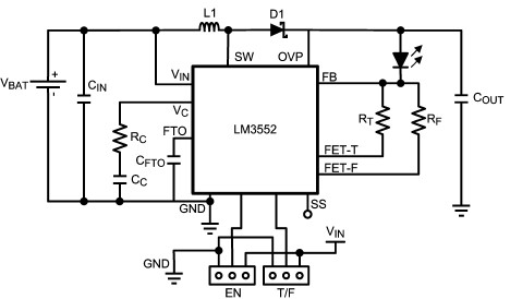
For this LED driver electronic project, a DC power supply circuit is required to provide an output voltage between 2.7V and 5.5V. The supply voltage must be applied between Vin and GND. The T/F jumper connects the T post...