
Cable TV amplifier
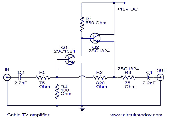
The described cable TV amplifier circuit employs a straightforward design based on two transistors, which are critical components in achieving the desired amplification. The first transistor, designated as T1, serves as the primary amplifying stage, capable of providing a gain of up to 20 dB. This level of amplification is particularly beneficial for cable television applications, where maintaining signal integrity is essential for clear audio and video output. The second transistor, T2, is configured as an emitter follower. This configuration is advantageous as it increases the current gain without significantly affecting the voltage gain, thus ensuring that the output signal can drive subsequent stages or loads effectively.
The circuit is optimized for use with 75 Ohm coaxial cables, which are standard in many cable TV installations. The operational frequency range of the amplifier is specified up to 150 MHz, making it suitable for typical cable television frequencies. The suggestion to utilize the 2SC2570 transistors is noteworthy, as this component is known for its low noise characteristics, which can enhance the overall performance of the amplifier by minimizing interference in the audio and video signals.
In terms of additional modifications, the inclusion of a 6-turn close-wound air core coil can further refine the circuit's performance. This coil, constructed from 18 SWG super enameled copper wire, can be strategically placed to improve signal filtering and stability. Proper placement between the capacitor (C2) and resistor (R5) junction and ground may help in reducing unwanted noise and enhancing the quality of the amplified signal.
Questions regarding the circuit's application in Wi-Fi signal amplification highlight the need for careful consideration of frequency ranges and component specifications. The original design is not tailored for the 2.4 to 2.5 GHz frequency band, which is typical for Wi-Fi signals. Using this circuit for such purposes may not yield the desired results, especially when attempting to extend coverage over a significant distance, such as 10 km. The performance of multiple circuits in series for Wi-Fi amplification would require extensive testing and potentially different design considerations to ensure adequate gain and stability at higher frequencies.
Finally, the issue of poor picture quality on a TV card when another television is in use suggests that the amplifier's gain may not be sufficient to handle multiple loads simultaneously. This scenario emphasizes the importance of ensuring adequate gain to maintain signal quality across all connected devices, particularly in shared setups where multiple devices may draw from the same signal source.This is a very simple cable TV amplifier using two transistors. This amplifier circuit is most suitable for cable TV systems using 75 Ohm coaxial cables and works fine up to 150MHz. Transistor T1 performs the job of amplification. Up to 20dB gain can be expected from the circuit. T2 is wired as an emitter follower to increase current gain. Hi Chary try using 2SC2570 for both the transistors. You can find the difference in the noisey channels both in audio and video or atleast in audio (the frying noise with audio will get reduced). Finally you may try a 6 turns close wound air core coil of 6mm dia with 18 SWG super enameled copper wire, between C2, R5 junction and ground.
I cant getting any changes in quality of picture, and I am using Transformer with rectifier and capacitor for providing 12v supply. please solve my problem, I wanted to ask whelther this circuit would be ideal to amplify wifi signals around 2.
4 to 2. 5 Ghz. I was working on a project in which i have to spread my wifi signals in 10km radius, i can use this circuit in series to amplify signal many many times, ill use atleast 15 of these circuits in series Actually, I have a Television and Computer TV Card in my home. When My dad watch TV, then my TV Card display poor quality Picture. Otherwise it is good. May be it is happennig for less line gain when running two sets (Television+TV Card). 🔗 External reference
Related Circuits
This is a very simple, low cost, Hi-Fi quality power amplifier. You can build it 5 ways, like it is shown in the table (from 20 W to 80 W RMS). The first thing that you must do, is...
This module is an essential addition to the Modular Preamplifier Control Center when more than two sources need to be connected to the preamplifier chain. Four high-level inputs can be selected using SW1 and routed to the output. The...
Can be directly connected to CD players, tuners and tape recorders. Simply add a 10K Log potentiometer (dual gang for stereo) and a switch to cope with the various sources you need. Output power: well in excess of 25Watt...
It is a single stage class A MOSFET design with the right gain and a low output impedance. Here we don't have the limitations of the Zen amps (at least in the single-stage implementations) regarding speaker compatibility. A single...
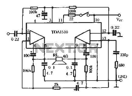
TDA1510 is an audio power amplifier from Philips. This integrated circuit (IC) includes features such as load short protection, open load detection, and an overheat protection circuit. It offers stable output voltage, excellent ripple rejection performance, requires fewer external...

An amplifier designed to drive Sennheiser HD-600 headphones, which have a relatively high impedance. This design ensures ample voltage is available for driving the headphones. Given the large dynamic range of the headphones, the system is engineered to be...
Warning: include(partials/cookie-banner.php): Failed to open stream: Permission denied in /var/www/html/nextgr/view-circuit.php on line 713
Warning: include(): Failed opening 'partials/cookie-banner.php' for inclusion (include_path='.:/usr/share/php') in /var/www/html/nextgr/view-circuit.php on line 713