
Hi-Fi power amplifier with MJ3001 and MJ2501


More: - Before the first "turning on" you must short circuit the inputs of the amp, and put a mA-meter on the output, then turn the amplifier on, and tune the R13 pot, to decrease the DC current on the output, to some µA-s, or in a lucky situation to zero. I was able to decrease it to 10 µA.
This power amplifier is designed to deliver high-fidelity audio output while maintaining a low-cost structure. The amplifier can be configured in five different ways, allowing for output power ranging from 20 W to 80 W RMS, depending on the specific requirements of the application.
Key components include the output transistors, T3 and T4, which are critical for the amplifier's performance. The transistors used, MJ3001 and MJ2501, are known for their reliability and efficiency in audio applications. It is essential to measure the current gain (hfe or β) of these transistors prior to assembly. A mismatch in the hfe values greater than 30% can lead to significant distortion and a lack of clarity in the sound output. It is recommended to use matched pairs of transistors to ensure optimal performance.
Before powering on the amplifier for the first time, it is crucial to take specific precautions to avoid damaging the circuit. The inputs of the amplifier should be shorted, and a milliampere meter should be connected to the output. This setup allows for monitoring of the output current during the initial power-up. Once the amplifier is powered on, the adjustable resistor R13 should be tuned to minimize the DC offset at the output. Ideally, this offset should be reduced to a few microamperes, or in an optimal scenario, to zero. Successful adjustment can result in a DC output current as low as 10 µA, which is acceptable for high-fidelity audio applications.
Overall, this amplifier design provides a straightforward approach to building a high-quality audio amplifier with careful attention to component matching and initial setup procedures, ensuring a clear and accurate sound reproduction.This is a very simple, low cost, Hi-Fi quality power amplifier. You can build it 5 ways, like it?s shown in the table (from 20 W to 80 W RMS). The first thing that you must do, is to measure the end transistors (T3 and T4) amplifying coefficient, the hfe or ?. If their disagreement is bigger than 30 %, the amplifier would not give a clear sound. I used MJ3001 and MJ2501 transistors, and this disagreement was around 5%. - Before the first ?turning on? you must short circuit the inputs of the amp, and put a mA-meter on the output, than turn the amplifier on, and tune the R13 pot, to decrease the DC current on the output, to some uA-s, or in a lucky situation to zero. I was able to decrease it to 10 uA. 🔗 External reference
Related Circuits
The amp is rated at 100W into a 4 Ohms load, as this is typical of a "combo" type amp with two 8 Ohm speakers in parallel. Alternatively, you can run the amp into a "quad" box (4 x...
A power supply circuit for the Sega Game Gear, intended for inclusion in your circuit collection. A more detailed explanation can be found on the website. The power supply circuit for the Sega Game Gear is designed to provide the...
This circuit is a modified version of a function-generator circuit. It features a battery-powered sine wave generator that can be continuously adjusted from 100 Hz to 10 kHz. The described circuit utilizes a sine wave generator to produce a continuous...
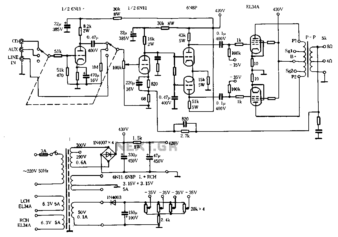
The Ml00 circuit is a typical tube circuit, functioning as a preamplifier. Its input stage utilizes a common cathode amplifier, followed by an inverter stage, culminating in a power amplifier that has been enhanced from a standard connection. This...
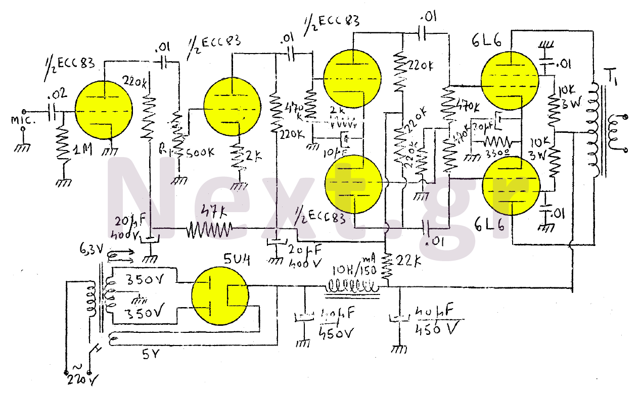
The amplifier in this design is rated at 30 Watts and is intended for use with a microphone. It is compatible with a crystal microphone and can be utilized for speeches, lectures, as a transmitter modulator, and in applications...
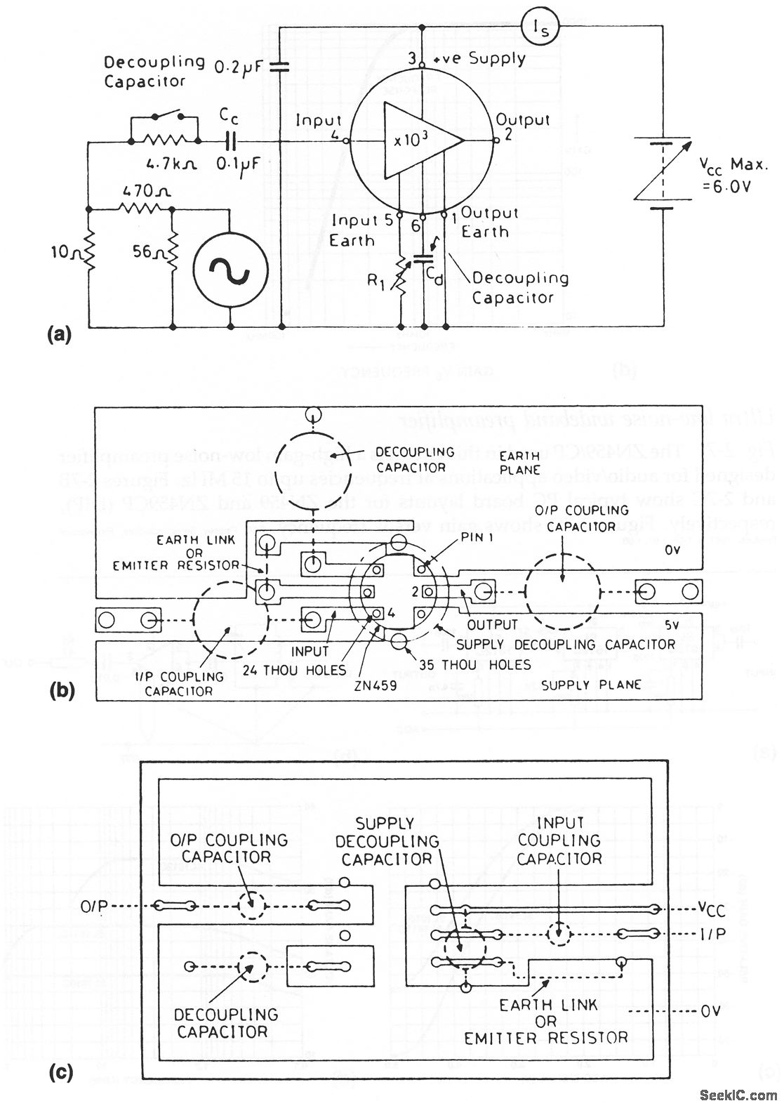
The ZN459/CP utilized in this circuit is a high-gain, low-noise preamplifier intended for audio and video applications at frequencies reaching up to 15 MHz. Figures 2-7B and 2-7C illustrate typical printed circuit board layouts for the ZN459 and ZN459CP...