
Camera power supply circuit

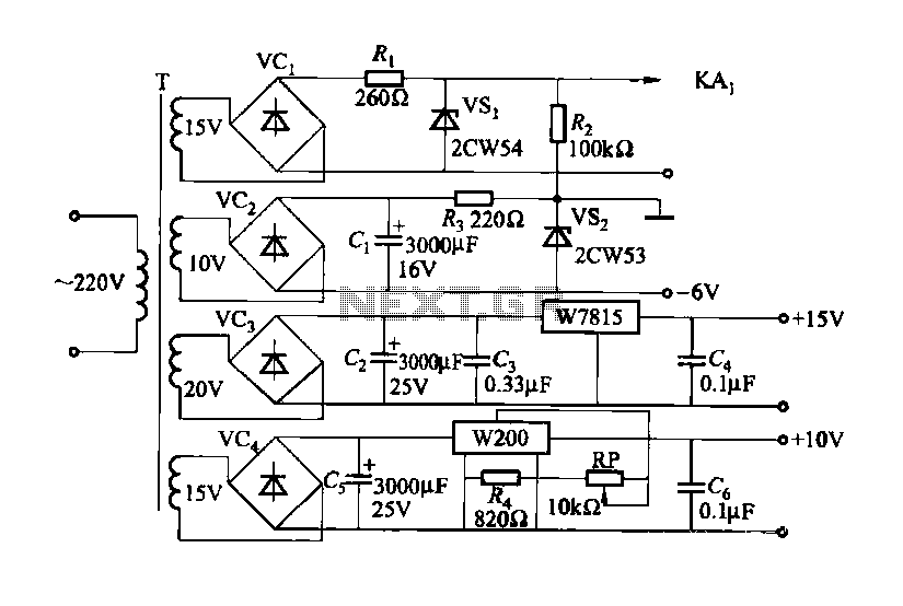
The camera power supply circuit is critical for ensuring that the camera operates effectively and reliably. It typically consists of various components designed to regulate the voltage and current supplied to the camera. A stable voltage control integrated circuit serves as the core of this power supply, providing a consistent output voltage that meets the camera's operational requirements.
The circuit may include input capacitors that filter incoming voltage to remove noise and transients, ensuring a clean power supply. Additionally, a rectifier may be employed to convert AC voltage to DC voltage, which is essential for most camera systems. The output of the rectifier is then smoothed using filter capacitors to minimize ripple voltage, further stabilizing the power supply.
The integrated circuit used in the power supply may feature built-in protection mechanisms such as over-voltage protection, thermal shutdown, and short-circuit protection to enhance the reliability of the camera. The output voltage is typically adjustable, allowing for compatibility with various camera models that may have differing voltage requirements.
Furthermore, the circuit design may include feedback mechanisms that monitor the output voltage and adjust the control signal to the integrated circuit, ensuring that the output remains within specified limits despite variations in load or input voltage. This feedback loop is essential for maintaining the stability of the power supply under different operating conditions.
In summary, the camera power supply circuit is a well-engineered assembly that guarantees the delivery of reliable power to the camera, utilizing a combination of integrated circuits, passive components, and protective features to ensure optimal performance and longevity of the camera system. Camera power supply circuit Shows the camera power supply circuit, the normal power supply in order to make the camera work properly, the power supply circuit is composed of a stable pressure control integrated circuit constituted.
Related Circuits
This document outlines a CMOS circuit designed for time adjustment in a spot welder. The circuit allows for the selection of a number of cycles, ranging from 1 to 99, with practical applications typically using around 10 cycles. The...
During experiments with various receivers and amplifiers powered by "free energy," it was discovered that connecting the audio amplifier to the receiver using only two wires for audio signals and supply voltage is more convenient. This setup allows the...
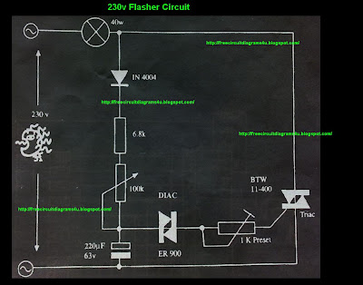
This circuit operates at 230V and can be utilized for party decoration purposes. It is sourced from an old circuit book titled "100 Circuit Book." The components include DIAC ER 900 and TRIAC BTW 11-400. The circuit is designed to...

This is a simple water level alarm circuit made using a 555 timer IC. The circuit will produce an alarm when the water level reaches a preset level. The water level alarm circuit utilizing a 555 timer IC is designed...
The car battery charging current is automatically limited to 4.2A. If there is a 600mV voltage on R1 (indicating 4A flowing through it), the T1 transistor begins to conduct. This prevents excessive charging current as the base current of...
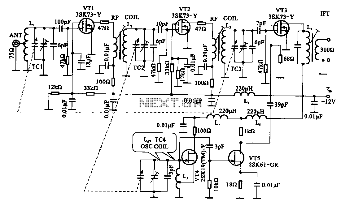
The FM radio circuit is represented by a double-gate MOS field-effect transistor. The high-frequency amplifier is a bipolar MOS field-effect transistor amplifier consisting of transistors VT1 and VT2. VT3 serves as the mixer. The local oscillator is formed by...