
Can a homebrew FET circuit replace a NTC

The proposed circuit design utilizes a power MOSFET to effectively manage the current flow to the bulb, substituting the traditional NTC thermistor. The circuit configuration consists of a few key components: the power MOSFET, a relay for gate discharge, resistors, and capacitors to shape the timing characteristics.
The power MOSFET serves as the primary switch, controlling the power delivered to the bulb. To ensure proper operation, the gate voltage must be sufficient to saturate the MOSFET, typically around 5V for high current TO-220 packages. A resistor (R1) is connected to the gate to limit the current and control the turn-on characteristics, while a second resistor (R2) is employed to manage the discharge time of the gate capacitance, influencing the soft start duration.
The relay, in this case, the Magnecraft W172DIP-7, is integrated into the circuit to facilitate the rapid discharge of the gate capacitor when the circuit is turned off. This addition addresses the long turnoff time observed in the initial design, allowing for a more responsive system while maintaining simplicity. The relay's placement is critical, ensuring that it does not interfere with the physical operation of the Mag's cammed reflector.
The time constant of the circuit can be adjusted by modifying the values of R1 and R2. Increasing R1 will extend the startup time, while decreasing R2 will lengthen the discharge time, allowing for fine-tuning of the soft start and turnoff characteristics. The design aims to achieve a balance between a visually appealing soft start and a reasonable turnoff period, enhancing user experience while minimizing component complexity.
Overall, the circuit is designed to be cost-effective, using readily available components, and aims to provide a reliable solution for users experiencing issues with NTC thermistors in their lighting applications. Further testing and community feedback will refine the design, ensuring it meets the practical needs of its users while remaining straightforward and efficient.Design cicuit using a power mosfet to replace the NTC (thermister) that many Mag623 users employ to prevent their bulbs from flashing. Although inexpensive and easy to hook up, NTC`s run quite hot. They are also affected by ambient temperature, require a cool down period and generally have a tolerance +/-20%.
I was hoping a simple FET circuit would be a practical solution. And by simple, I mean 6 or 7 discreet components, readily available, less than $20, and easy to tailor to one`s specific needs. It has a terribly large time constant and for good cause: I don`t have a scope. So I needed a prolonged, clearly visible soft start to verify functionality. Well, I got what I wanted. The startup delay was nearly 3 seconds, with a soft start period of approx. 1/2 second. Here is the breadboard: (It`s nasty looking, you may want to wear safety googles) Unfortunately, the turnoff cycle is nothing short of comical.
130 seconds to shutoff! From 0 to 110 seconds, the lamp appears fully lit. From 110 to 120 seconds, the lamp slowly turns off. But it takes another 10 seconds before there is no visible glow from the filament. I had to laugh. My next step was to Google search CPF to determine how short of a soft start period would work. Perhaps if 20ms was adequate, a turnoff period of 10-12 seconds wouldn`t seem so bad. But in my searching, I came across this thread (and others as well): Clearly, this has all been done before. But they too had to confront the long shutoff period, which meant more components and complexity. To keep my circuit simple, I had to find a simple solution to discharging the gate capacitor. I then recalled I had an assorted collection of small signal PCB relays. Would a relay work Would a relay fit Turns out a relay works just fine! A Magnecraft W172DIP-7, plus a resistor, does the trick. And despite the length of the relay, there is no interference with the Mag`s cammed reflector. I now wonder if I can fit all of this stuff into the ubiquitous KIU switch. To that end, I`ve ordered a couple of KIU kits and a couple of 64623 bulbs. I don`t yet have a tri-bore host or battery pack to complete a 623, and I`m not sure I ever will. While I don`t doubt for a second that it must be a Hell of a lot of fun to have an armor piercing 3000-5000 lumens in one`s hand, I`m not convinced such a monster is for me.
For now, I`m content with the challenge of replacing a NTC with a "simple" FET solution. WOW, vantastic job. Looks really really promising. Please do the board view again with the relay in place. We have some reall good EE types here that as you have found have created solutions, but we can always use a new one and especially if it is a simple and straight forward as yours. I am sure they will chime in with comments as this comes along. TF 3W Lux, TF 3 W Cree, Fenix L2D-CE, Fenix L2T, Fenix P1D, Fenix P3D-CE w/3x123 tactical body, P3D-CE Q5 w/2x123 tact bdy, 3D & 3C Mag w/Malkoff, Modded ROV Swivel Sportsman with KPR112 bulb & 3xCR123 Connect the + side of the bulb to the same side of the switch as R1.
That will also eliminate any potential issue with leakage current when the light is off. You also need to make sure the voltage on the gate is enough to cause the transistor to saturate and turn fully on, but not too much. Vgs is to saturate a FET is usually ~5V in a high current TO-220 power FET. You`ve got more than enough voltage on that pin. Increasing R1`s value and decreasing R2`s value will lengthen the start up time, and decrease the discharge time.
Stereodude - like other FET approaches (AW, AWR, JM-SST), I want the FET to handle both the large on and 🔗 External reference
Related Circuits
The circuit consists of an ultrasonic transmitter and a receiver that operate at the same frequency. Ultrasonic piezoelectric transducers serve as the output and input devices, respectively, with their frequency of operation determined by the specific devices used. The...

Is there a circuit that can be used to make a DC motor move randomly backward and forward, stop for a period, and then start again? Any assistance and ideas would be greatly appreciated. Research how to wire up...
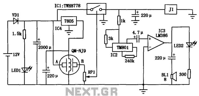
The alcohol detection alarm controller circuit is illustrated in the figure. It utilizes the QM-NJ9 alcohol gas sensor, which detects the presence of alcohol vapors. When alcohol is detected, the resistance between the AB-QM-NJ9 decreases, causing the wiper of...
This USB circuit utilizes an integrated circuit (IC) to convert digital voice data into an analog signal, enabling it to be used with headphones. The output can also be amplified through a power amplifier to drive speakers. The IC...

The following circuit illustrates a Frequency Voltage Converter Circuit. This circuit is based on the LM331 IC and operates with a supply voltage of 15V DC. The Frequency Voltage Converter Circuit utilizes the LM331 integrated circuit, which is designed for...
The high durability of a light-emitting diode (LED) makes it suitable for ON/OFF indicator applications. However, there are limitations regarding low operating voltage. Light-emitting diodes (LEDs) are semiconductor devices that emit light when an electric current passes through them. Their...