
Frequency Voltage ConverterCircuit Using The LM331 IC

The Frequency Voltage Converter Circuit utilizes the LM331 integrated circuit, which is designed for converting frequency signals into corresponding voltage levels. The circuit typically employs a triangular waveform generator, which serves as a reference frequency input. The LM331 IC processes this input and generates an output voltage that is proportional to the frequency of the input signal.
Key components of the circuit include resistors, capacitors, and the LM331 IC itself. The resistors determine the conversion range and the sensitivity of the output voltage, while capacitors are used for filtering and stability. The circuit's design allows it to handle a wide range of frequencies, making it suitable for various applications, including signal processing and instrumentation.
The operation of the circuit can be summarized as follows: an input frequency is applied to the LM331, which then generates a DC output voltage that reflects the frequency of the input signal. The output voltage can be further processed or utilized in other circuits, depending on the requirements of the application. Additionally, the circuit can be calibrated to ensure accuracy and precision in the frequency-to-voltage conversion process.
Overall, the Frequency Voltage Converter Circuit based on the LM331 IC is a versatile and effective solution for applications requiring frequency measurement and conversion to voltage signals.The following circuit shows about Frequency Voltage Converter Circuit. This circuit based on the LM331 IC, Features:15V DC as the accumulation .. 🔗 External reference
Related Circuits
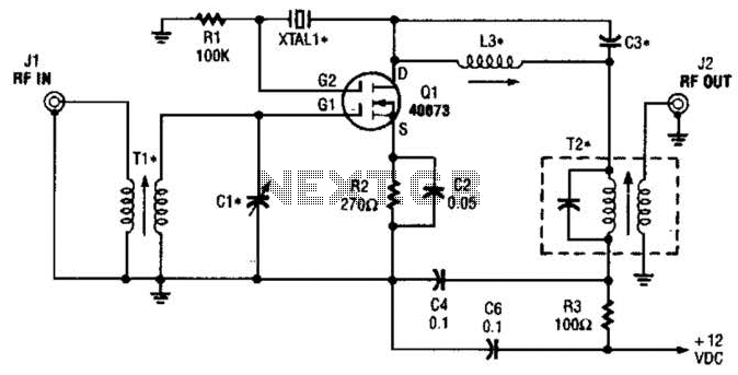
The second gate (G2) of a MOSFET can be utilized to integrate a crystal oscillator within the same stage as a frequency mixer. While this technique is common in tube technology, it is rarely implemented in dual-gate MOSFET circuits....
A substation capable of consuming 100 MVA with 375 kVA, 60 Hz input and 132 kV at 50 Hz using the same power. The challenge is to convert the 60 Hz input to 50 Hz, including a wiring diagram. To...
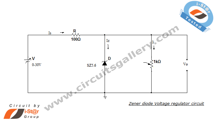
A Zener diode regulator is a fundamental electronic circuit valuable for hobbyists. This circuit provides a regulated output voltage, suitable for biasing other circuit components. The Zener diode operates in the reverse breakdown region, maintaining a nearly constant voltage...
To make an LED function, a voltage source is required that exceeds the LED's forward bias voltage, which is typically greater than 1.5V (approximately 2V for red LEDs). To effectively operate an LED, it is essential to provide a voltage...

This design circuit is for a tone/frequency detector (decoder) that can detect the presence of a signal with a specific tone. The output of the circuit will be active if the signal matches the tone of an internal oscillator....
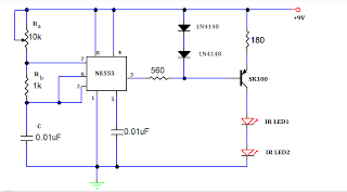
A TV remote jammer circuit using the NE555 timer IC. This device allows users to watch their favorite TV channels without interruptions, as it prevents others from changing the channel using a remote control when the circuit is activated....