
Capacitance Meter

The capacitance meter circuit utilizes two 555 timer integrated circuits (ICs) configured in an astable mode. The first 555 timer (IC1) generates a continuous square wave output, the frequency of which varies based on the value of the capacitor under test (C). The second 555 timer (IC2) is used to convert the frequency signal from IC1 into a readable voltage level, which can then be displayed on a digital voltmeter or an analog meter.
In this configuration, the frequency output from IC1 is determined by the formula:
\[ f = \frac{1.44}{(R1 + 2R2)C} \]
Where:
- \( f \) is the frequency in Hertz,
- \( R1 \) and \( R2 \) are the resistances connected to the timing pins of the 555 timer,
- \( C \) is the capacitance in farads.
By carefully selecting the resistor values (R1 and R2), the circuit can be calibrated to measure capacitance values ranging from 100 pF to 10 µF. The output frequency is then fed into IC2, which is configured to measure the frequency and convert it into a proportional voltage. This voltage can be easily interpreted as a capacitance value on a display device.
The circuit also includes a power supply section, typically using a 9V battery or an external DC power source, ensuring that the 555 timers operate within their specified voltage range. Additional components, such as diodes for protection and capacitors for stabilization, may be included to enhance circuit reliability and accuracy.
Overall, this capacitance meter circuit provides a practical and efficient method for measuring capacitance in electronic components, making it a valuable tool for engineers and hobbyists alike.Capacitance Meter Circuit Using 555 It directly reads capacitance in the range 100pF to 10µF. IC1 and IC2 operate as an astable (with frequency.. 🔗 External reference
Related Circuits
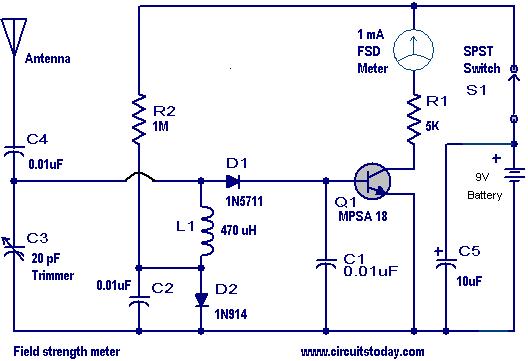
This is a practical field strength meter designed to measure the strength of AM radio signals. The circuit is particularly beneficial for individuals assembling radio transmitters, especially during the tuning of the final stage to achieve maximum range. Essentially,...
A milliamp meter can function as a voltmeter by incorporating a series resistance. The required resistance is calculated by dividing the full-scale voltage reading by the full-scale current of the meter movement. For instance, using a 1 milliamp meter...
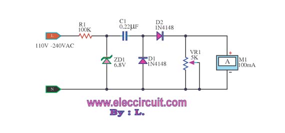
This meter displays the frequency of a power generator, which operates at a voltage range of 110V-240V and a frequency range of 10-100Hz. The output sine waves are converted to square waves. The described frequency meter is designed to accurately...
Power input is to a 7805 5 volt regulator. A pair of LEDs is connected between the 5 volt supply and ground, with current limiting resistors in series and one pin on the AT90S2313 shunts the current through one...
This is a circuit schematic diagram for VU meters. The circuit is controlled by the IC TL072 and follows a measurement circuit as per the National general application. The input circuit around IC1 is designed for adaptation and amplification...
An electronic project to construct an LC meter project kit of exceptional accuracy to measure both inductance and capacitance—an inductance meter and capacitance meter all in one unit. It is readily available as a comparatively inexpensive kit, which is...