
Analog Milliamp Meter Used as Voltmeter circuit

To implement this conversion effectively, the circuit design must ensure that the milliamp meter is properly calibrated to operate within the desired voltage range. The series resistor, which is critical for this adaptation, should be connected in series with the meter. The resistor's value is determined based on the maximum voltage to be measured and the full-scale current rating of the meter.
In the example provided, the 1 milliamp meter has a full-scale current of 0.001 A. To measure up to 10 volts, the series resistor can be calculated as follows:
\[ R = \frac{V_{max}}{I_{full-scale}} = \frac{10V}{0.001A} = 10,000 \, \Omega \]
This means a 10K ohm resistor must be used in series with the meter. When a voltage of 10 volts is applied across the combination of the resistor and the meter, the current flowing through the circuit will be 1 milliamp, which corresponds to the full-scale reading of the meter.
It is essential to select a resistor that can handle the power dissipation, calculated using the formula:
\[ P = I^2 \cdot R \]
For this application:
\[ P = (0.001A)^2 \cdot 10,000 \, \Omega = 0.01W \]
A resistor rated for at least 1/8 watt (0.125W) would be suitable, providing a safety margin.
When constructing the circuit, ensure that the connections are secure and that the resistor is rated for the appropriate power level. The meter should be calibrated after assembly to confirm accuracy across the intended voltage range. This configuration allows for a simple yet effective method to extend the functionality of a milliamp meter into the realm of voltage measurement, making it a versatile tool in various electronic applications.A milliamp meter can be used as a volt meter by adding a series resistance. The resistance needed is the full scale voltage reading divided by the full scale current of the meter movement. So, if you have a 1 milliamp meter and you want to read 0-10 volts you will need a total resistance of 10/.001 = 10K ohms..
🔗 External reference
Related Circuits
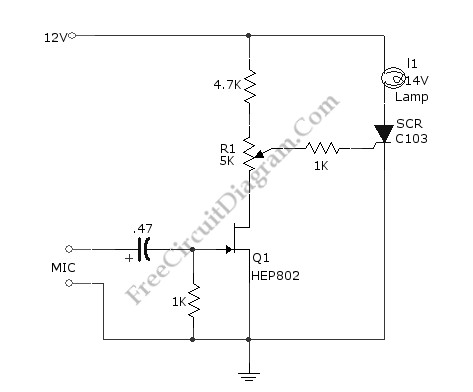
This simple circuit illustrated in the schematic diagram activates the switch using sound. It can be utilized for various applications, such as automatic (sound-controlled) disco lights or car LED light shows. The transistor Q1 amplifies the audio from the...
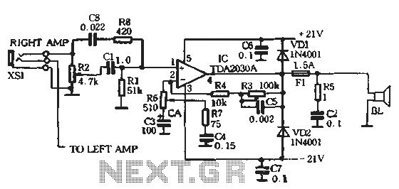
The circuit comprises two main components: the Lisheng power amplifier and the rectifier filter section. The stereo audio power amplifier circuit diagram, depicted in Figure 5-85, illustrates only one channel, with the other channel being identical. The audio signal...
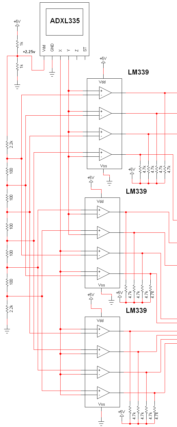
The schematic for this project is extensive, and the complete schematic is displayed below. It is divided into two sections: the analog and digital sections. The schematic illustrates the analog-to-digital conversion circuit, which includes 12 comparators—6 for the X-axis...
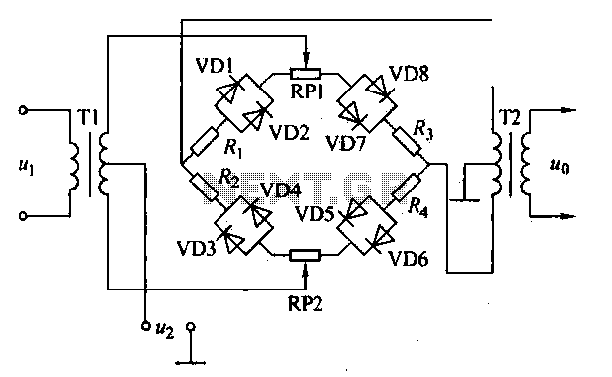
An AM diode ring circuit consists of four diodes arranged in a ring configuration, commonly referred to as a diode ring modulator circuit. This circuit offers significant advantages due to the characteristics of the diodes and the use of...
Assistance is required regarding the circuits provided below. The focus is on an ultrasonic receiver circuit that utilizes two ultrasonic components. The ultrasonic receiver circuit is designed to detect ultrasonic waves, typically in the frequency range of 20 kHz to...
In an audio amplifier, the quality of sound depends on several factors, including the quality of active and passive components, circuit configuration, and layout. The selection of components is influenced by the constructor's budget. Discrete active components like transistors...