
CAPACITANCE METER

The circuit consists of two main functional blocks: the oscillator (U1a) and the measurement unit (U1b). The oscillator generates a continuous waveform, typically a square wave, which is modulated in width based on the capacitance being measured. This modulation occurs through a feedback mechanism that adjusts the duty cycle of the output signal relative to the capacitance value.
U1b, the measurement section, is responsible for interpreting the modulated signal generated by U1a. It employs a pulse-width modulation (PWM) technique to convert the varying width of the pulses into a voltage signal that can be easily read by the meter. The linearity of the meter ensures that the average voltage output is a direct representation of the capacitance value. This is particularly important for applications requiring precise capacitance measurements, as it allows for straightforward calibration and interpretation of results.
Meter M1 is designed to capture the average voltage of the PWM signal, which reflects the duty cycle of the output from U1a. Due to its mechanical frequency response characteristics, M1 is optimized to provide accurate readings at lower frequencies, making it suitable for this application. The overall design ensures that the circuit can effectively measure unknown capacitance values with a high degree of accuracy, leveraging the relationship between pulse width and capacitance to deliver reliable results.
In summary, this circuit design effectively integrates an oscillator and a measurement unit to facilitate the conversion of unknown capacitance into a readable voltage signal, allowing for practical and efficient capacitance measurement in various electronic applications.U1a is an oscillator and U1b the measurement part of the circuit. It converts unknown capacity into a pulse-width modulated signal the same way an automotive dwell meter works. The meter is linear so the fraction or percentage of time that the output is high is directly proportional to the unknown capacitance (CX in the schematic).
Meter M1 reads the average voltage of those pulses since its mechanical frequency response is low compared to the oscillator frequency of U1a. 🔗 External reference
Related Circuits
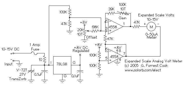
This circuit is used to measure the voltage on a 12V (nominal) lead acid rechargeable battery system. It was specifically designed for use in solar powered systems, but is general enough that it can be used for automotive or...
SWR, or standing wave ratio, is the ratio of the amplitude of a partial standing wave at an antinode (maximum) to the amplitude at an adjacent node (minimum). SWR is a critical parameter in RF (radio frequency) engineering, particularly in...

A capacitance multiplier simulates a high-capacitance capacitor for analog signal processing. By utilizing a Digital-to-Analog Converter (DAC), it is possible to emulate... A capacitance multiplier is a circuit configuration that effectively increases the apparent capacitance seen at its output compared...
The LED current drive is regulated and programmable, which eliminates the need for current-limiting resistors. The integrated circuit (IC) features an adjustable voltage reference and an accurate ten-step voltage divider. The LED current drive circuit is designed to provide precise...
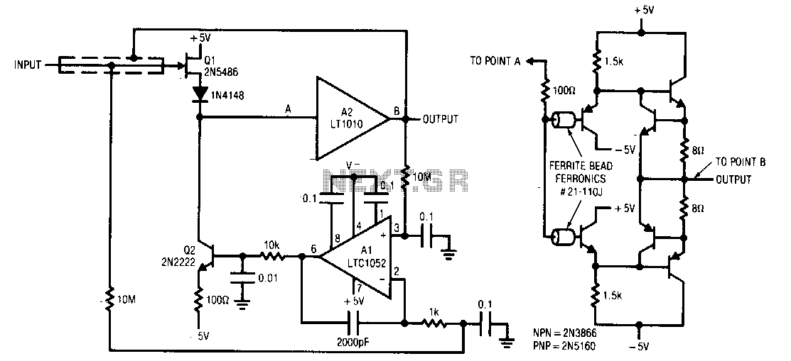
Q1 and Q2 form a simple, high-speed FET input buffer. Q1 operates as a source follower, while Q2 serves as a current-source load that regulates the drain-source channel current. The LT1010 buffer is utilized to provide output drive capability...

This circuit is designed to measure the inductance of an inductor labeled LX. The output of the circuit generates a TTL square wave, with its frequency being directly related to the inductance being measured. The output from the inductance...