
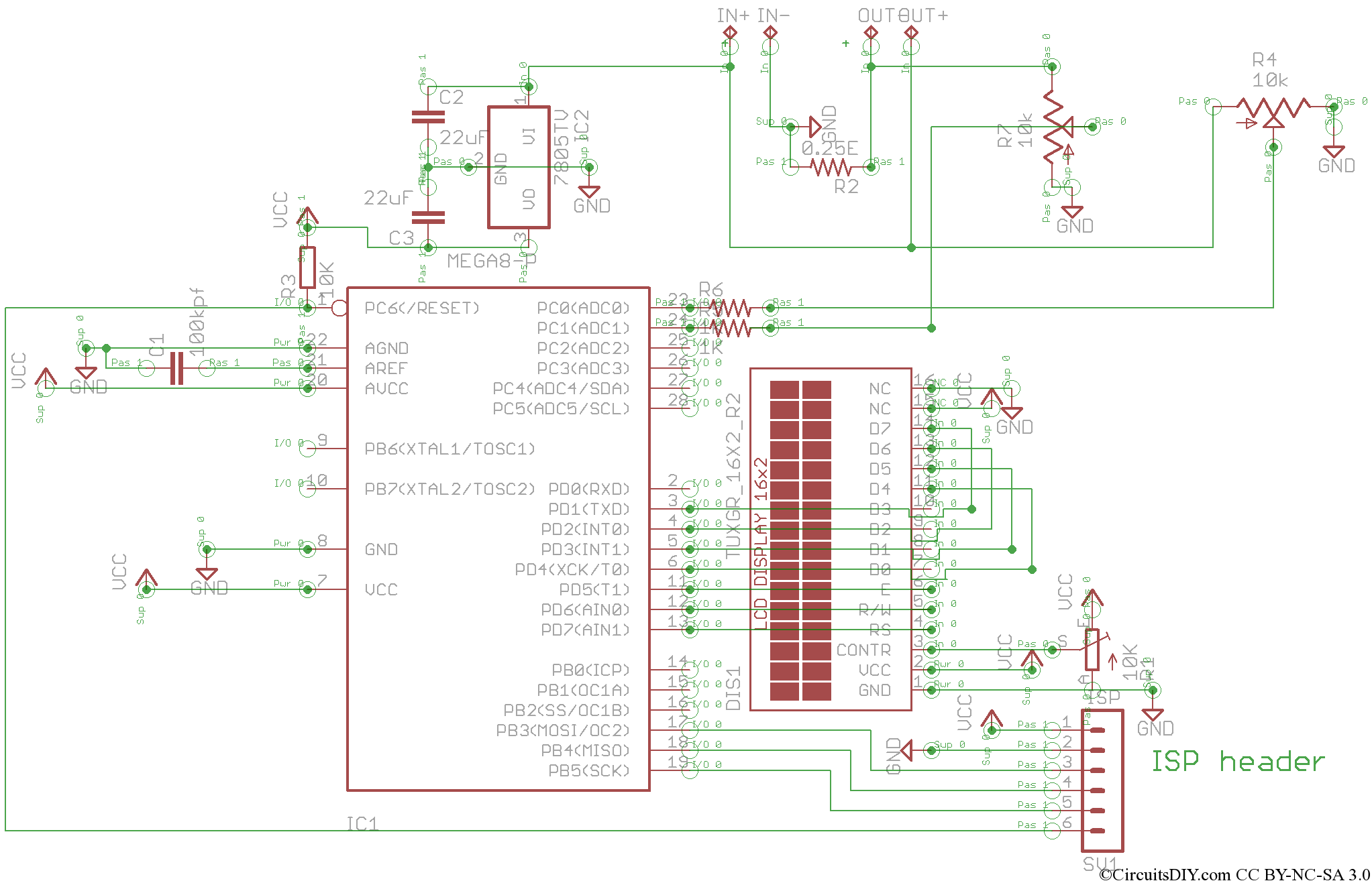
PIC16F88 SWR Meter

SWR is a critical parameter in RF (radio frequency) engineering, particularly in the design and analysis of transmission lines and antennas. It quantifies the efficiency of power transfer from a source to a load, indicating how much of the signal is reflected back toward the source due to impedance mismatches. A perfect SWR of 1:1 signifies that all power is transmitted to the load without any reflections, while higher values indicate increasing levels of reflected power, which can lead to signal degradation and potential damage to RF components.
To measure SWR, an SWR meter is typically employed. This device analyzes the voltage standing wave pattern along the transmission line, calculating the ratio based on the maximum and minimum voltage levels. Understanding and minimizing SWR is essential in ensuring optimal performance in RF systems, as excessive reflections can result in overheating of transmitters, reduced efficiency, and distortion of the transmitted signal.
In practical applications, various techniques are utilized to achieve a low SWR, including properly matching the impedance of antennas to the transmission line, using matching networks, and employing baluns or transformers where necessary. Additionally, regular monitoring of SWR can help identify issues in the system that may arise over time, ensuring reliable operation in communication systems, broadcasting, and other RF applications.SWR or standing wave ratio is the ratio of the amplitude of a partial standing wave at an antinode (maximum) to the amplitude at an adjacent node (minimum).. 🔗 External reference
Related Circuits
This is the V2 update of the Atmega8 Volt-Ammeter. This new version features several upgrades, including low power consumption, improved amperage display resolution while using a low-value drop resistor, and a much smaller PCB size of only 5cm x...
The ROMs or PROMs must contain the correct code to convert data from the NE5037, which serves as the address for the ROMs or PROMs, into the appropriate segment driver codes. The displayed temperature can easily be converted to...
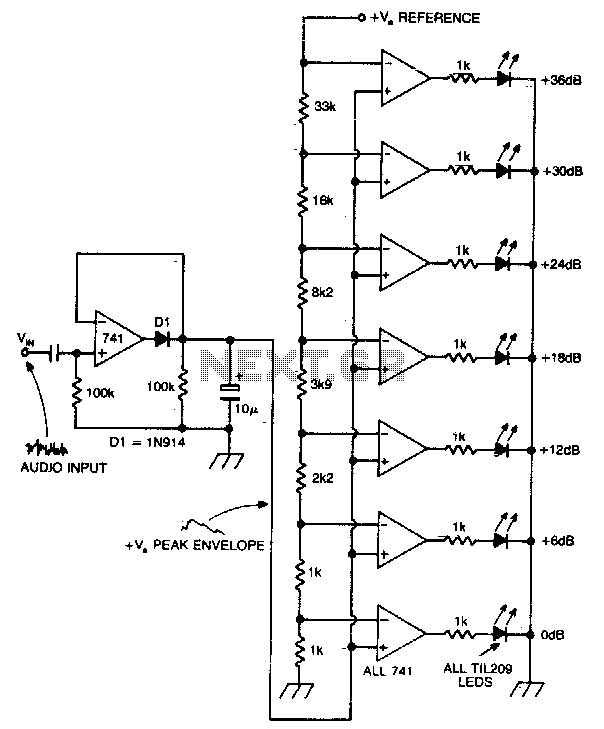
A vertical column of LEDs is configured so that as the audio signal level rises, an increasing number of LEDs illuminate. The LEDs are arranged in increments of 6 dB. The circuit features a fast response time and a...
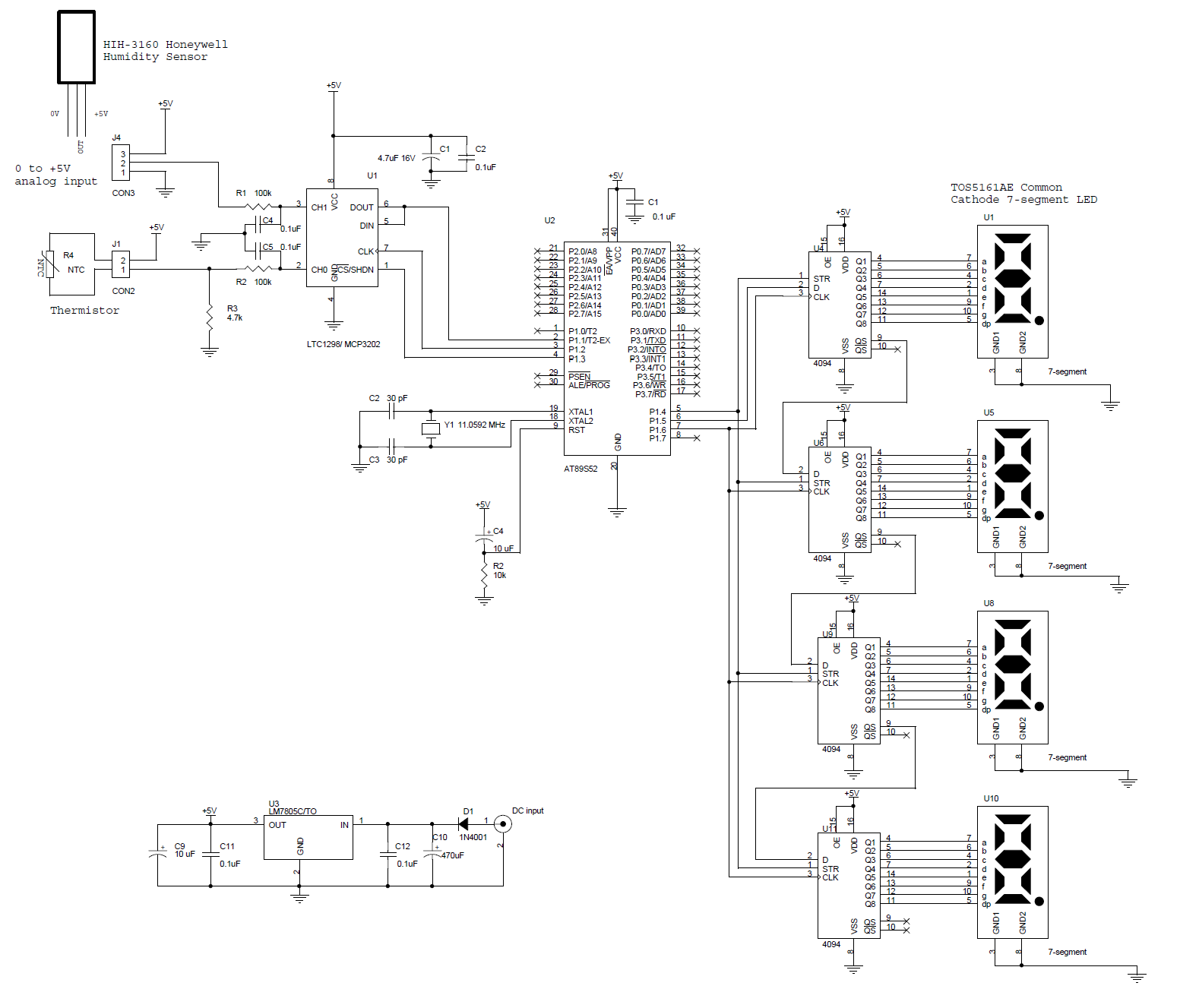
This circuit features a microcontroller AT89S52 paired with a 12-bit ADC LTC1298. The programs are written in C and include digital filtering, interfacing with a 0.5-inch 7-segment LED display. The thermometer provides a sensitivity of 0.1°C. The hardware block...
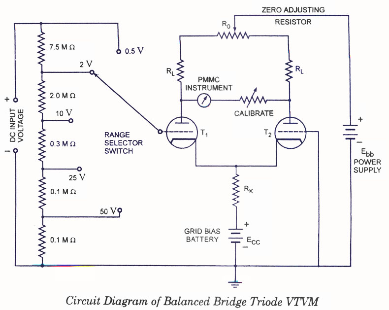
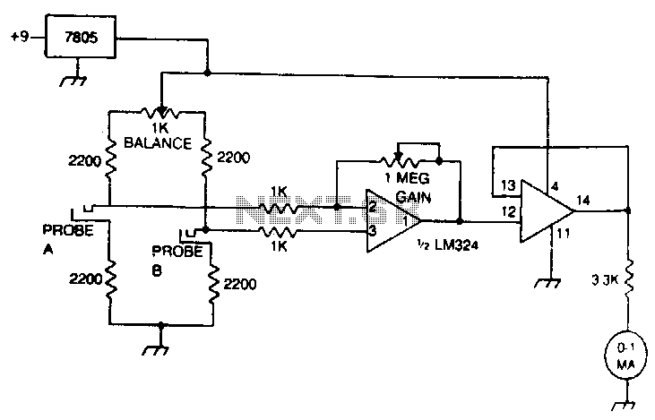
Voltmeters can be utilized for measuring both direct current (DC) and alternating current (AC) voltages and are widely used. These voltmeters are available in two types: vacuum tube and transistorized. In the vacuum tube version, two identical triodes, T1...

The Bus Pirate is an effective tool for exploring new chips with a PC, eliminating the need for integration into a microcontroller project. Upon receiving the unit, testing it with the MMA7456L accelerometer featuring an I2C/SPI interface from Freescale...