
Capacitance Meter Circuit

A capacitance meter is a specialized device used to measure the capacitance of capacitors in electronic circuits. It is a valuable tool for diagnosing and troubleshooting electronic components, ensuring they function within their specified parameters. The capacitance meter operates by applying a known voltage to the capacitor and measuring the resulting current flow, allowing it to calculate the capacitance value in farads, microfarads, or nanofarads.
When using a capacitance meter, it is important to observe the following operational principles: the meter should be calibrated regularly to ensure accurate readings, and it should be used in accordance with the manufacturer's instructions. The device typically features a digital display for easy reading of capacitance values, as well as various ranges to accommodate different capacitor sizes.
Moreover, advanced capacitance meters may include additional functionalities, such as the ability to test ESR (Equivalent Series Resistance), leakage current, and even the ability to test components in-circuit. This versatility makes capacitance meters invaluable for tasks ranging from simple hobby projects to complex professional repairs and assessments.
In summary, a capacitance meter is a fundamental tool in the electronics field, providing critical measurements that support effective circuit design, repair, and maintenance.Capacitance meter is one instrument that you should have in your toolbox if you are an electronics hobbyist, or if you`re a professional electronic technician.. 🔗 External reference
Related Circuits
This project is currently under construction and has not been validated for functionality. A signal generator, resistor, and oscilloscope were utilized to measure the value of an inductor for a battery charger project. In the search for an affordable...
The motor control circuit depicted in the image utilizes the LM339 comparator among other components. When the input control signal is high (PWL), comparators A and A3 activate the power amplifier circuit, which consists of A4, VT5, and VT6,...

The preamplifier circuit is designed to offer appropriate loading for phono cartridges with reluctance. It achieves a gain of approximately 25 dB at 1 kHz (converting an input of 2.2 mV to an output of 100 mV). The circuit...

This simple circuit can create an 18 LED flasher to decorate a Christmas tree. The white, blue, and red LEDs flash at different rates to provide a colorful display. It is a light-sensitive circuit, automatically activating in the evening...

This circuit produces a soft turn-on for halogen lamp filaments upon powering up. The MOSFET used is a BUZ10, which has a resistance of 0.2 ohms. Resistors R1, R2, and capacitor C1 set the turn-on rate, while diode D1...
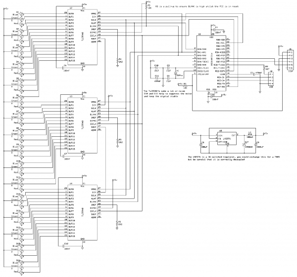
This project creates an RGB LED VU Meter controlled via USB by a host machine running Windows 7 or Vista. It serves multiple purposes: it demonstrates the ability to read audio information from the Windows machine and transmit it...