
Halogen Lamp Protector Circuit

The circuit employs a BUZ10 MOSFET to control the power delivered to halogen lamp filaments, allowing for a gradual increase in brightness rather than an abrupt illumination. This soft start feature is particularly beneficial for extending the lifespan of the halogen lamps, as it reduces thermal stress on the filaments during power-up.
Resistor R1 and resistor R2 form a voltage divider that influences the gate voltage of the MOSFET, effectively controlling the turn-on time. The time constant for the turn-on process is determined by the values of R1, R2, and the capacitance of C1. A larger capacitance or higher resistance values will result in a slower increase in voltage at the gate, leading to a softer turn-on.
Capacitor C1 plays a crucial role in the timing of the turn-on process. When power is applied, C1 charges through the resistors, gradually increasing the gate voltage until it reaches the threshold voltage of the MOSFET, causing it to turn on. The diode D1 is connected in parallel with C1 and ensures that when the power is turned off, C1 discharges quickly, allowing the MOSFET to turn off rapidly and preventing any residual voltage that could keep the lamp glowing.
The design of this circuit is essential for applications where a sudden surge of current could damage sensitive components or reduce the lifespan of the halogen lamps. By utilizing the BUZ10 MOSFET, which has a low on-resistance of 0.2 ohms, the circuit minimizes power loss and heat generation during operation, enhancing efficiency and reliability. Overall, this soft turn-on circuit is a practical solution for controlling halogen lamps in various lighting applications. This circuit, produces a soft turn-on for halogen lamp filaments upon powering up. MOSFET used is a BUZ10, which has 0.2 Rm on. Rl, R2, and CI set the turn-on rate and D1 discharges CI at turn-off.
Related Circuits

The motion sensor circuit depicted in Figure 1 operates when a 12-volt power supply is applied to the input point. The motion sensor circuit is designed to detect movement and trigger a response based on the presence of motion...
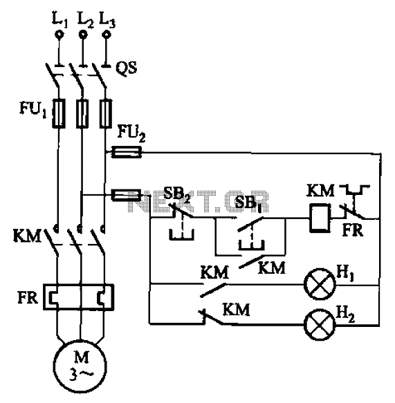
The circuit illustrated in FIG. 3 + 20 features SBi as the start button, SB2 as the stop button, Hi for run lights, and Hz for down lights. The subsequent circuit description aims to prevent tediousness by omitting the...
For example, I do not understand the process of demodulation or the modulation itself, and so on. Is there someone who can understand this circuit? Could you please assist me? The circuit in question likely involves a modulation and demodulation...
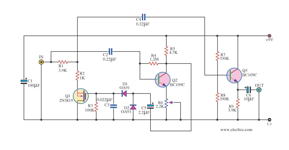
In audio systems, noise signals are generally undesirable, and efforts are often made to eliminate them. Transistors can be utilized effectively for this purpose due to their availability and low noise characteristics. The following circuit serves as a Noise...

Basic features include an internal 512k-bit EEPROM, allowing for continuous recording and playback at any time, with long-term retention of voice data after power loss. The voice recording time is 20 seconds, and it supports segmented recording and playback....
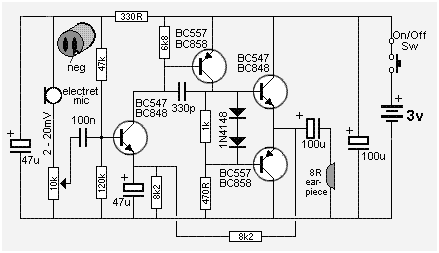
The following circuit presents a Mini Audio Amplifier Circuit Schematic Diagram. Features include a power consumption of less than 3mA, a small output, and the use of a push-pull configuration. The Mini Audio Amplifier Circuit is designed to amplify low-level...