
Capacitance meter using LM2917

The LM2917 capacitance meter circuit operates by converting the frequency of an input signal into a corresponding voltage output, which is indicative of the capacitance value being measured. The IC is designed to work with a specific input range and requires careful attention to component values and connections to ensure proper functionality and safety. The circuit's design necessitates a step-down transformer to reduce the high voltage AC supply to a manageable level for the LM2917, ensuring that the IC operates within its specified voltage range.
The inclusion of resistors R1, R2, R3, and R4 is critical for establishing the correct voltage levels and for calibration purposes. R1 allows for fine-tuning of the output voltage to accurately reflect the measured capacitance. R2 serves as a load resistor, facilitating the voltage measurement across the capacitor. R3, while intended for voltage division, poses a risk if not properly implemented, as it connects to high voltage AC, which can lead to circuit failure or hazardous situations.
Additionally, the suggestion to use a 555 timer as a clock source instead of relying on direct mains voltage is prudent, as it enhances safety and reliability. The 555 timer can generate a stable 60 Hz signal needed for the frequency-to-voltage conversion process, removing the direct dependency on potentially dangerous AC mains voltage.
In summary, while the LM2917 capacitance meter circuit provides a foundational understanding of capacitance measurement, it requires careful design consideration, particularly in power supply management and component selection, to ensure safe and effective operation. The schematic, as it stands, serves an educational purpose and highlights the importance of thorough circuit design practices in electronics engineering.The circuit diagram of a simple capacitance meter using IC LM2917 is shown here. The LM2917 is a high gain monolithic frequency to voltage converter IC from National Semiconductors. Even though the main application of LM2917 is in tachometers, it can be also used for a variety of applications like this. Capacitance values from 0. 01uF to 0. 1uF can be measured using this circuit. The capacitance to be measured is connected between pin 2 of the IC and ground. The output voltage available across resistor R2 will be proportional to the Cx and it will be displayed by the meter. Resistor R1 can be used for calibrating the circuit. I think that something is missing in the diagram, I might not be a electronic wizard, but how is possible that you connect R3 50k to the line input R3 goes to the first pin of IC LM2917 the IC will blow up, on your face.
If you look carefully you see that pins 5, 6 of the IC go to 15VDC supply. That means that we have to insert a power transformer in my case of 125vac;with a secondary of 18vac at line input 110vac 60HZ;then use a rectifier bridge and all that stuff to rectify and clean every peak of the ac converted to dc The input of the 110 VAC 60 HZ; a step down transformer should be used, 18-20vAC output, then a bridge rectifier and the proper electrolytic capacitors to filter the remain AC;the problem is he didn`t include that information and we don`t know the values of those components I see that the other side of R3 is connected to 110 V AC 60HZ ;if I connect it to the AC line the tester will blow on my face;it have to be an error;there is not a step down transformer to bring the line to 15-18 V Ac and then a rectifier circuit to bring it to clean DC For M1 You can use a 1 m. a. meter and connect a 10K resistor in series with the meter, By Ohm`s Law E=I x R= 1 m, a. x 10K =10 volts. If you need a 5 volt Meter use a 5K resistor( 2 10K resistors in parallel ) All I did here was convert a ammeter into a D.
C. Voltmeter. This is a possible solution to the 10V FSD PROBLEM. i WOULD STICK WITH A 555 Timer @ 60 Hz Rather than the A. C. VOLTAGE DIVIDER . I couldn`t agree more with Steven`s concern on A. C, Voltage Issue, thE 555 Solution is a much safer alternative! Why not try using a step down transformer around 8 to 12 vac Good Building and Stay Safe! Hi FSD means full scale division. that is you have to use a 0 to 10 volt range meter. you can use any good DMM in 10 volt full range ( 0 to 1. 99 volt in a 3 and half digit multimeter or a DVM) I am worried by the indication in the schematic of a direct connection to the live mains. This is extremely dangerous when done by a novice circuit builder. Much safer is to derive the 60 Hz clocking reference from the lower voltage secondary winding of the power supply that is used to feed the 15 volts DC working voltage to the LM2917.
Resistors R3/R4 form a 10:1 mains voltage divider so 8 to 12 volts AC could be applied directly to pin 1. An alternate application would be to use a LM555 as a cheap 60 Hz oscillator. The term FSD means simply Full Scale Deflection and is mostly meaningless in the modern era of digital readouts.
As presented, this circuit is only of educational value and not a practical capacitance meter for the workshop. 🔗 External reference
Related Circuits
The circuit utilizes two quad voltage comparators (LM339) to illuminate a series of eight LEDs that indicate volume levels. Each of the eight comparators is biased at increasing voltages determined by a voltage divider, allowing the lower right LED...
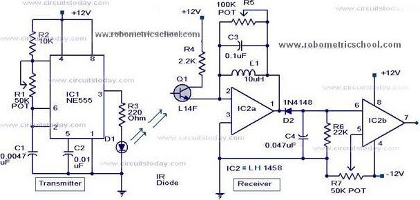
All components used in the Moving Sensor/Detector Schematic Diagram utilize the IC NE555 and the Phototransistor L14F. The primary component in this circuit is the IC NE555, along with an IR LED, the Phototransistor L14F, and the IC LM1458....
It is very interesting and convenient to be able to control everything while sitting at your PC terminal. Here, a simple hardware circuit and software is used to interface a 7-segment based rolling display. The printer port of a...

The frequency pulses originating from the mains supply are safely insulated by capacitors C1 and C2, along with inductor L1. These pulses are amplified by transistor Q1, while diodes D1 and D2 limit any peak voltages at the input....
Direct-reading SWR meters automatically compute the ratio of forward and reverse powers, eliminating the need for sensitivity adjustments. Several years ago, a meter was built based on a design by G3WPO, which was sold as a kit by Cirkit....
The tools used in this circuit are designed to create a noisy atmosphere. This circuit is relatively simple and is controlled by two 555 timer integrated circuits (ICs), assisted by other discrete components such as resistors and capacitors. The...