
Noise-producing sound effects using NE555

The circuit consists of two primary components: the tone generator (U2) and the modulation source (U1). The 555 timer IC (U2) is configured in astable mode, allowing it to produce a continuous square wave output. The frequency of this output can be modified by adjusting the resistance value of the potentiometer R5, which is connected in the timing network of the 555 timer. This enables the user to select different tones that will be transmitted through the speaker.
The modulation of the tone is achieved by the second 555 timer IC (U1), which is also configured in astable mode to generate a sawtooth waveform. This waveform serves as the modulation signal for the output of U2. The frequency of the sawtooth waveform can be adjusted using potentiometer R4, allowing for control over the modulation rate. The interaction between the tone generated by U2 and the modulation from U1 results in a complex audio output that varies in pitch and amplitude, creating the desired noisy atmosphere.
The circuit's design allows for flexibility in sound generation, making it suitable for applications such as sound effects in electronic devices or artistic audio installations. The use of discrete components, such as resistors and capacitors, in conjunction with the 555 timer ICs, provides reliability and ease of assembly. The schematic would illustrate the connections between the two 555 timers, the potentiometers, and the speaker, demonstrating how the modulation and tone generation work together to create the final audio output.Tools that created this is to produce noisy atmosphere. This circuit is quite simple, this circuit controlled by two 555 timer IC is assisted by other discrete component resistors and capacitors. The first 555 timer U2 will generate a tone which can be heard on the frequency can be set using a potentiometer R5.
next U2 output is given directly to the speaker or speakers. But in this case the speaker will not produce a constant tone. This is because the U2 is modulated by the sawtooth waveform generated by U1. The following is a schematic drawing: Sawtooth frequency that can be set using the potentiometer R4. The end result will be obtained modulated signal high and low tones that can be arranged with R5 while the modulation rate set by R4. 🔗 External reference
Related Circuits
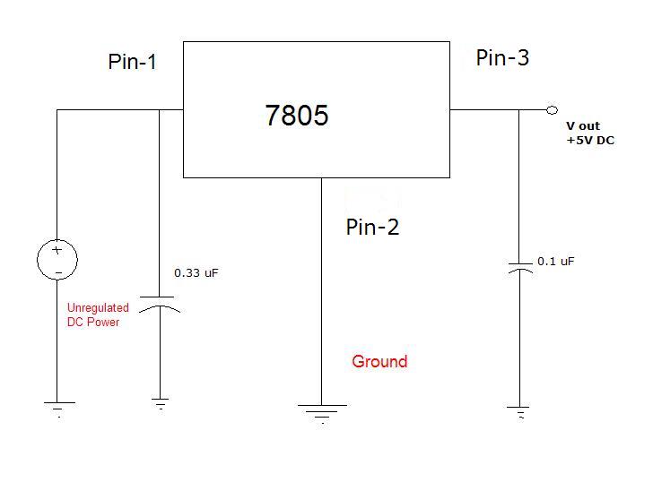
Many different devices require DC power and thus need an I.T.E power supply. I.T.E stands for "Information Technology Equipment." An example of such a device is an iPod speaker system that is no longer functional, which originally came with...
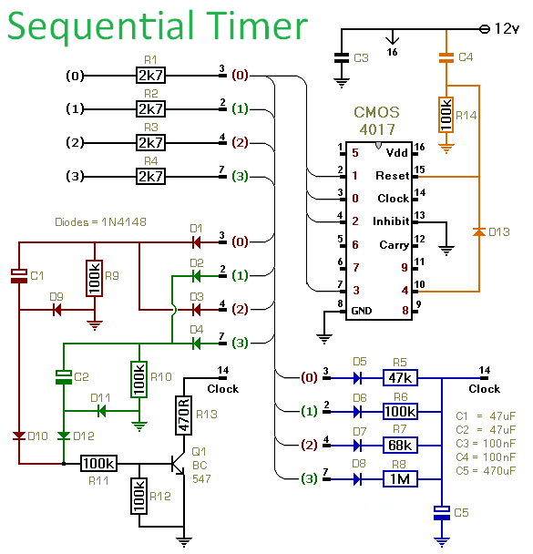
This circuit utilizes a CMOS 4017 decade counter to generate a sequence of four distinct events, with the capability to expand the sequence to nine or ten events. Each event's duration is independently controlled. The inclusion of D13 allows...
Testing whether a transistor is shorted or open is typically performed using an ohmmeter. The test involves checking if current can flow between the base and emitter or the collector. To effectively test a bipolar junction transistor (BJT) for shorted...

The circuit utilizes a 555 Integrated Circuit (IC) configured as a delay circuit. It transitions from a low to a high state after a button (SB) is pressed, initiating a delay before the output terminal goes high. The output...
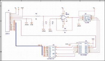
This example demonstrates the design of a circuit that incorporates both analog and digital components, features multiple power planes, and utilizes a single ground plane that is divided into analog and digital sections while maintaining a common reference point. The...
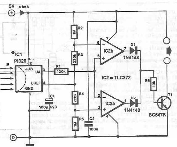
This infrared detector circuit utilizes the PID20 integrated circuit manufactured by Siemens, which converts thermal radiation into electrical impulses. It includes an operational amplifier and several electronic components. The output signal at pin 3 is compared to a reference...