
Capacitor Esr Measurer

The circuit for measuring the equivalent series resistance (ESR) of a capacitor is a specialized design that utilizes a combination of resistors, an inverting operational amplifier, and a square-wave generator. The square-wave generator operates at a frequency of 50 kHz, providing a stable AC signal to the capacitor-under-test. The current waveform produced is approximately ±180 mA, which is sufficient to create a measurable voltage drop across the equivalent series resistance of the capacitor.
Resistors R1 and R2 are crucial components in this circuit, as they help establish the current path and influence the voltage drop across the capacitor. R3 acts as a variable resistor or potentiometer, allowing for fine adjustments to be made until the voltage drop across the equivalent series resistor is nullified. This nulling process is essential for obtaining an accurate reading of the capacitor's voltage, V0, which represents the pure voltage across the capacitor without the influence of the ESR.
The output voltage V0 is minimized by adjusting R3, and the position of the potentiometer is recorded. The value of R2, typically set to 1 ohm, is then multiplied by the noted position of R3 to calculate the ESR of the capacitor. This method ensures that the measurement is accurate and accounts for any variations in the circuit.
The circuit is designed to operate with capacitors biased at approximately 7.5 V. It is important to note that this circuit is not suitable for lower-voltage capacitors, as they may not function correctly under these conditions. Additionally, the design allows for the adjustment of R2 to measure different ESR ranges. However, when using smaller values of R2, it is necessary to increase the current level to maintain a reasonable voltage across R2, which may require the incorporation of a buffer stage to prevent loading effects that could distort the measurements.
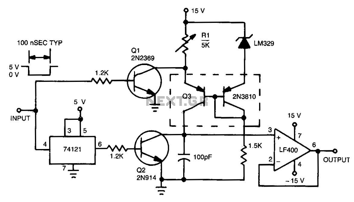
This ESR measurement circuit is particularly useful for capacitors greater than 100 µF, as lower capacitance values can introduce significant ripple voltage, which adversely affects measurement accuracy. Therefore, careful consideration of the capacitor's specifications and the circuit parameters is essential for obtaining reliable ESR readings. The equivalent series resistance (ESR) of a capacitor can be measured using this circuit and an ac voltmeter. Ul fun ctions as a 50-kHz square-wave generator. It drives a current waveform of about ±180 mA in the capacitor-under-test, through Rl and R2. When R3 is adjusted to the proper value, the voltage drop across the equivalent series resistor is precisely nulled by the inverting amplifier (U2). Thus, V0 is the pure capacitor voltage which is the minimum voltage that can be produced at V0. To make an ac voltage measurement, adjust R3 until V0 is minimized. Then, note the position of the potentiometer and multiply it by the value of R2, 1 in this case. That product equals the capacitor"s ESR. The capacitor is biased at about 7.5 V. Lower-voltage capacitors won"t work with this circuit. By changing the value of R2, other ranges of ESR can be measured. However, for small R2 values, the current level should be increased to keep a reasonable voltage across R2.
This requires some sort of buffer. The circuit is intended for capacitors greater than 100 The ripple voltage gets large for smaller values and accuracy decreases. 🔗 External reference
Related Circuits

A capacitor step-down DC power supply circuit is presented. This circuit eliminates the need for power transformers, utilizing capacitive voltage drop rectification and regulation, which significantly reduces the overall size of the circuit. The circuit includes a capacitor step-down...

The capacitor is composed of two sheets of aluminum foil. It is essential to keep the foil within the plastic packets and connect them using crocodile clips, ensuring that the clips do not touch each other. The initial frequency...
This circuit functions by charging a small capacitor using a constant-current source when a measurable pulse is present. The dual PNP transistor Q3 acts as the current source, with its output current determined by dividing the LM329 reference voltage...
The NCP5810D is a dual-output DC/DC converter capable of generating both positive and negative voltages. This device is optimized for powering modules such as AMOLED display drivers, where high output voltage accuracy, regulation, signal integrity, and compact design are...
Leaving aside the complex chargers, "stuffed" electronics capacitor charger is one of the best connections. Charging current is limited by the resistor (or other element of the changing excess energy into heat), but the reactance of the capacitor to...

The PACO C-25 differs from the Healthkit IT-22b in that it tests both regular and electrolytic capacitors and utilizes a 40 MHz oscillator to allow a rough measurement of capacitance through a bridge circuit. In vintage vacuum tube equipment,...