
own capacitor

The described circuit utilizes a capacitor formed from two aluminum foil sheets, which serves as the primary component for generating pulse frequencies. The crocodile clips used for connections must be carefully positioned to avoid contact, as this can lead to short circuits or erroneous readings. The 4060 integrated circuit (IC) functions as a frequency divider, allowing the initial pulse frequency to be reduced significantly, with the output frequencies observable at various pins.
Pin 7 of the 4060 is designated for the highest frequency output, making it the primary observation point for pulse frequency analysis. As the probe is moved to pin 5, a noticeable halving of the frequency occurs, indicative of the division process inherent to the IC. This halving continues at pin 4, illustrating the systematic reduction of frequency across the outputs. The final output at pin 3 represents the slowest pulse frequency, providing a clear understanding of the frequency division process.
The investigation into the capacitor's behavior reveals that increasing the overlap area of the capacitor plates results in a change in pulse frequency, which can be monitored via the oscilloscope. This relationship between capacitor size and frequency is critical in understanding capacitive behavior in circuits. The addition of an audio amplifier stage enhances the experiment by converting frequency changes into audible sounds, allowing for a more engaging demonstration of the capacitor's properties.
Furthermore, the experiment highlights the role of insulators in capacitor performance. While the impact of insulator variation is not thoroughly explored, it is acknowledged that different materials can influence capacitance. Insulators such as polyester, polythene, and ceramic are commonly used in non-polarized capacitors, while polarized capacitors utilize aluminum oxide as an insulating layer. Understanding these materials and their effects on capacitance is essential for designing and implementing effective electronic circuits.The capacitor consists of two sheets of aluminium foil. Leave the foil inside the plastic packets and make connections using crocodile clips. The crocodile clips must not touch each other. The initial frequency of the pulses can be divided by up to 214 times. Use the oscilloscope to probe the counter outputs. You will find the fastest pulses at pi n 7 of the 4060, with slower pulses at the other counter outputs. When you move the probe to pin 5, the frequency of the pulses is halved compared with the frequency at pin 7, and is halved again if you move the probe to pin 4. The slowest pulses can be observed at the final output of the counter, pin 3. Connect the probe to any one output. What happens to the frequency of the pulses on the oscilloscope screen when the area of overlap of the capacitor plates is increased It is nice to see the pulses on the oscilloscope screen, but it is more fun to hear the changes in the frequency of the pulses by adding an audio amplifier stage to your circuit: Once the circuit is complete, the sound produced will be quite loud.
The frequency should change when the area of overlap of the capacitor plates is changed, or when they are pressed closer together. A lower frequency means that the capacitor is taking longer to fill up and empty. In other words, lower frequencies indicate an increase in the size of the capacitor. The effect of changing the insulator between the capacitor plates is difficult to investigate properly in this experiment.
However, changing the insulator can change the size of the capacitor. Insulators used in making non-polarised capacitors include polyester, polythene and ceramic. A thin layer of aluminium oxide forms the insulating layer in most polarised capacitors. 🔗 External reference
Related Circuits
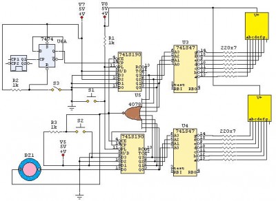
This is a 24-second countdown timer circuit designed for automatic control of electronic loads. The timer circuit utilizes fast 74LS Schottky integrated circuits (ICs). A 24-second countdown begins when switch S3 is off and switch S2 is pressed. Switch...
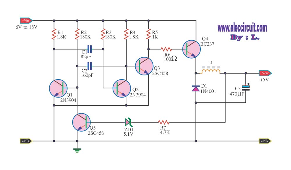
The circuit reduces voltage size or functions as a step-down voltage converter circuit, which is a DC regulated circuit model utilizing a switching converter. This design generates a specific voltage output. The step-down voltage converter, also known as a buck...
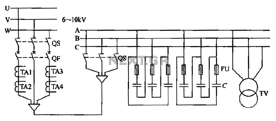
The compensation system is designed to focus on a high-pressure, high-voltage capacitor bank installed in the substation 6-10 kV bus. Compensation can only be implemented in this manner for the 6-10 kV bus before the reactive power on the...
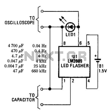
An LM3909 LED flasher functions as an oscillator, with the frequency determined by the capacitor connected to its terminals. The LED can be utilized to visually count frequency using a stopwatch for large capacitors (C > 500µF). The LM3909 is...
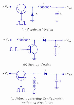
Switching voltage regulators include step-up, step-down, and polarity-inverting configurations, along with their working principles and circuit diagrams. Switching voltage regulators are essential components in modern electronic circuits, providing efficient voltage conversion. These regulators can be categorized into three main types:...
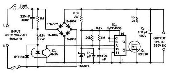
Universal power supply with a safe high-voltage capacitor power supply. Refer to that page to read the explanation about the related circuit diagram of the above power supply. The universal power supply circuit is designed to provide a stable output...