
Car Alarm Arming Beep Canceller

The circuit described utilizes a 555 timer integrated circuit (U1) configured in monostable mode to achieve the desired delay functionality. The 555 timer is a versatile component that can be used to generate precise timing intervals. In this application, it is triggered by the signal from the alarm system.
When the alarm is armed, it sends a short pulse (the "beep") to the circuit. This pulse is filtered by the resistor-capacitor (RC) network formed by R1 (1KΩ) and C1 (0.01μF), which helps to smooth out the signal and prevent false triggering. The output of the 555 timer will only activate the horn relay (K1) if the input signal remains high for a duration longer than the preset time, which is determined by the values of R2 (10KΩ) and C2 (100μF).
The delay is crucial; it ensures that only a sustained alarm signal, which is longer than 3 seconds, will activate the horn relay. This is achieved by charging the capacitor C2 through the resistor R2, which sets the timing interval. The output from the 555 timer is connected to the relay, which, when energized, will allow the horn to sound for genuine alarm situations.
Diodes D1, D3, and D4 (1N4004) are used for flyback protection to prevent voltage spikes from damaging the circuit when the relay is switched off. D2, the red LED, serves as a visual indicator that the circuit is powered and operational. The resistors R3 (15KΩ) and R4 (470Ω) are used for biasing and current limiting for the LED and other components in the circuit.
The entire assembly is mounted on a PCB, with appropriate connectors and wiring to interface with the vehicle's alarm system and the horn relay. This design offers a practical solution for users who wish to maintain the functionality of their car alarm while minimizing unnecessary noise from the horn during the arming process.It's a great convenience that most modern cars come with a built in alarm, however it is nothing but noise pollution that the horn sounds when the alarm is armed. Disconnecting the alarm system from the horn relay will eliminate this, but prevent the horn from sounding in the even of an actual alarm.
This circuit serves to silence the arming beep yet maintain the alarm by introducing a small delay into the signal. It sits between the alarm and horn relay. The alarm must provide a constant horn signal for at least 3 seconds before the horn relay is activated.
That way the quick "beep" will never activate the horn relay, while the constant alarm signal will. C1 1 0.01uF Ceramic Disc Capacitor C2 1 100uF 35V Electrolytic Capacitor R1 1 1K 1/4W Resistor R2 1 10K 1/4W Resistor R3 1 15K 1/4W Resistor R4 1 470 Ohm 1/4W Resistor D1, D3, D4 3 1N4004 Rectifier Diode D2 1 Red LED U1 1 555 Timer IC K1 1 SPST 12V Automotive Relay MISC 1 Board, Wire, Socket For U1, Case This circuit is by bob and was originally posted to the forum as Need Circuit Project to Improve Remote Car Alarm. 🔗 External reference
Related Circuits
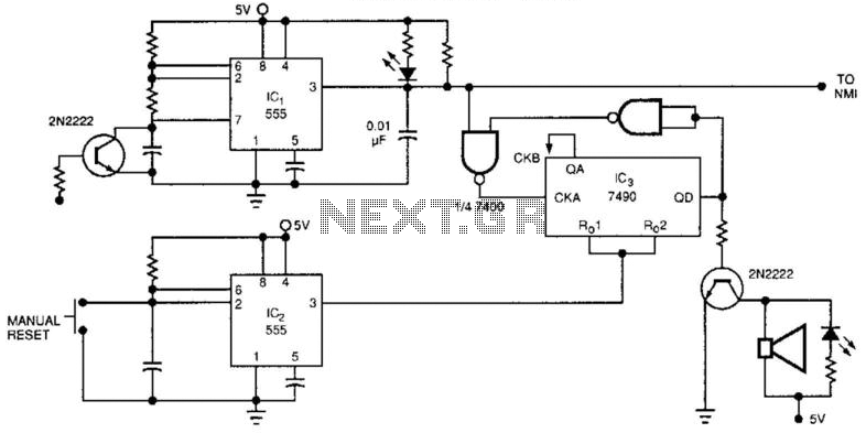
The watchdog timer includes a counter, IC3, alongside the standard retriggerable 555 timer, IC1. The counter will sound an audible alarm if the watchdog timer attempts to reset a specified number of times (8, in the case of the...
This is the complete wiring diagram for the 1997 Honda CR-V. It includes wiring diagrams for each electrical module of the Honda CR-V, such as the Rear Wiper/Washer Circuit, Front Wiper/Washer Circuit, Warning System Circuits, and the Supplemental Restraint...
This circuit diagram represents a radio-controlled system, commonly utilized in toy car applications for children. The circuit comprises two main components: the transmitter and the receiver circuits. The transmitter circuit generates radio signals through an oscillator circuit built with...
This circuit displays a sound generator that simulates the siren of a British police car. The circuit is constructed using two timer IC 555. The sound generator circuit designed to simulate a British police car siren utilizes two 555 timer...
Camping today often requires carrying various electronic devices for daily activities and entertainment. Typically, a charged lead-acid battery and a power inverter are utilized to ensure a well-organized trip, allowing family members to use their electronic devices comfortably. It...
This circuit, housed in a compact plastic enclosure, can be conveniently stored in a bag or handbag. A small magnet is positioned near a reed switch and is attached to the individual carrying the bag via a thin cord....