
Radio-controlled toy car

The transmitter circuit begins with the oscillator, which is responsible for generating a stable radio frequency signal. Transistor Q1 (9016) functions as the main active device in this oscillator configuration, providing the necessary gain and switching capabilities. The frequency of oscillation is finely tuned by the crystal Y1, ensuring that the emitted signals remain within the designated frequency band for radio communication.
The oscillator's performance is significantly influenced by the inductor components L1 and L2, which are carefully selected to resonate with the crystal frequency. These inductors, in conjunction with T1, form a tank circuit that is essential for maintaining the stability and purity of the oscillation. The design must ensure minimal distortion and a clean signal output, which is crucial for effective communication between the transmitter and receiver.
The receiver circuit is designed to capture the radio signals transmitted by the oscillator. It typically includes an RF amplifier to boost the received signal strength, followed by a demodulator that extracts the original control signals from the modulated carrier wave. The receiver's performance is equally critical, as it must effectively filter out noise and interference while maintaining the integrity of the control commands sent to the toy car.
The entire system is powered by a suitable DC power source, which must be regulated to ensure consistent operation of both the transmitter and receiver circuits. Proper grounding and shielding techniques should also be implemented to minimize electromagnetic interference, which can adversely affect the performance of the circuit.
Overall, this radio-controlled circuit diagram is a fundamental representation of how toy cars can be remotely operated, showcasing the essential components and their roles in the transmission and reception of radio signals. Understanding each part's function and interaction is vital for troubleshooting and enhancing the circuit's performance in practical applications.This circuit is a circuit diagram of the radio-controlled, usually in the toy car application children. Circuit diagram consists of 2 parts of the circuit sender and receiver circuits. To the circuit sending radio signals generated by the oscillator circuit formed by transistors Q1 9016, operating frequency of the oscillator is determined by the crystal Y1 is worth 27.145 MHz.
A very critical part of this oscillator circuit is T1, L1 and L2, which specifically discussed separately at the end of. 🔗 External reference
Related Circuits
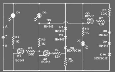
This circuit is designed to monitor the voltage level of a car battery. When the battery voltage drops to 11.5V or less, the transistor Q1 is activated, causing LED D1 to illuminate. When the battery voltage is between 11.5V...
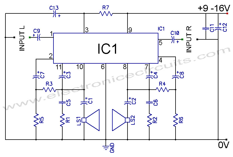
TDA2004 Car Battery 12W Stereo Amplifier Circuit. Its main features are low distortion, low noise, and high reliability of the chip. The TDA2004 is a highly integrated audio amplifier designed specifically for automotive applications. This circuit is capable of delivering...
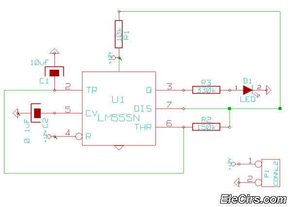
This is a very simple 555 timer circuit that serves as a straightforward theft deterrent, which may be just as effective. The idea is to have a flashing red LED indicate that your car is protected. This device can...
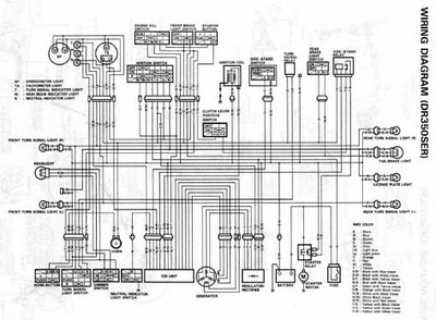
The following circuit illustrates the electrical circuit diagrams for the Toyota Supra. The diagrams indicate the point at which the power source is received. The electrical circuit diagrams for the Toyota Supra provide a comprehensive overview of the vehicle's electrical...
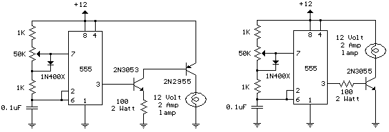
The schematic diagram illustrates a 12 Volt Car Lamp Dimmer Circuit Design utilizing a 555 Timer. This circuit can be employed to dim a standard 25-watt lamp. The 12 Volt Car Lamp Dimmer Circuit utilizes a 555 Timer in astable...
This circuit displays a sound generator that simulates the siren of a British police car. The circuit is constructed using two timer IC 555. The sound generator circuit designed to simulate a British police car siren utilizes two 555 timer...