
Car Alarm Arming Horn Beep Canceller

This circuit operates by utilizing a delay mechanism that is essential for distinguishing between temporary and sustained alarm signals. The design typically involves a monostable multivibrator, which generates a time delay. When the alarm is armed, the circuit monitors the output signal from the alarm system. If the alarm produces a brief "beep," the monostable multivibrator will not trigger the horn relay, as the duration of the signal is insufficient to meet the 3-second threshold.
In contrast, if the alarm system sends a continuous signal indicating an actual alarm condition, the monostable multivibrator will activate after the preset delay, allowing the horn relay to engage. This engagement activates the horn, providing an audible alert of the alarm status. The use of a capacitor and resistor in conjunction with the multivibrator helps set the timing parameters, ensuring reliable performance under different conditions.
In summary, this circuit effectively balances the need for a silent arming process while ensuring that genuine alarm conditions result in an audible alert, enhancing the overall effectiveness of the alarm system without compromising security.Disconnecting the alarm system from the horn relay will eliminate this, but prevent the horn from sounding in the even of an actual alarm. This circuit serves to silence the arming beepyet maintain the alarm by introducing a small delay into the signal.
It sits between the alarm and horn relay. The alarm must provide a constant horn signal for at least 3 seconds before the horn relay is activated. That way the quick "beep" will never activate the horn relay, while the constant alarm signal will. 🔗 External reference
Related Circuits
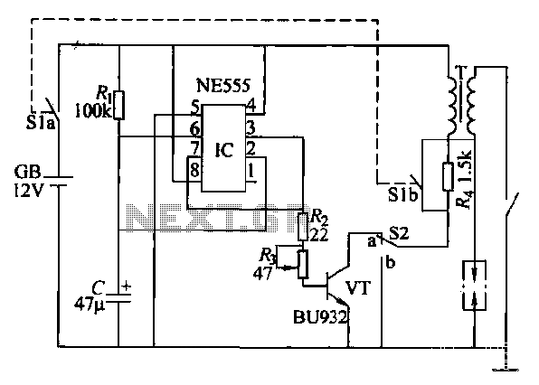
This paragraph describes an easy car alarm circuit that utilizes fewer components and is simple to produce. The circuit consists of an automobile anti-theft alarm system based on the NE555 timer, a power switch (VT), and a switch (S2),...
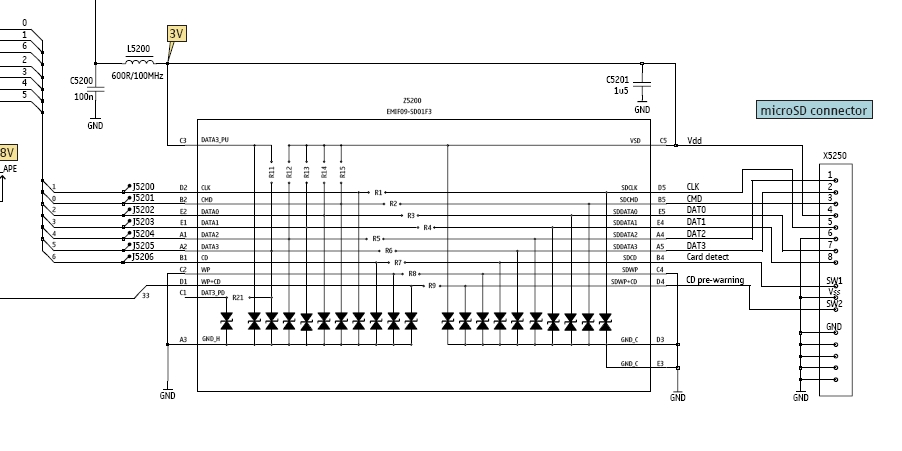
In this tutorial, the functioning of the memory card circuit in mobile phones will be explored. The previous post discussed the pin-outs and types of memory cards utilized in cellular devices. The accompanying block diagram illustrates how the removable...
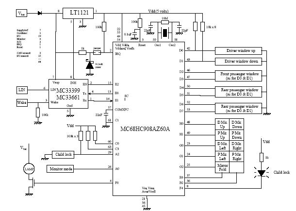
A car door differs from a calculator or a phone in that it makes sense to press more than one key at a time. The functionality of a car door can be compared to that of a multi-key input device,...
The SN75604, which features input control logic and requires only a single supply rail, can be utilized in light activation sensors and alarm drivers. The device's Vqq and enable inputs are connected to a voltage lead from the light...
Charger for car battery power supply. Refer to the webpage for an explanation of the power supply-related circuit diagram. The battery charger indicator circuit described above enhances the appearance of a simple battery charger. This circuit serves as a...
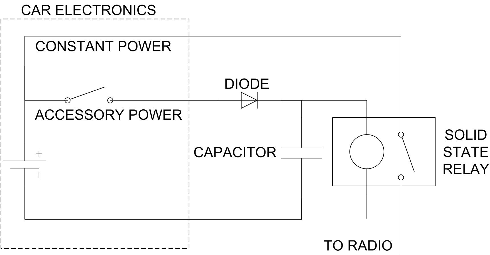
The car radio has the issue of losing track of the CD playback position when the ignition is turned off. This can be problematic during long journeys, especially when leaving an audiobook playing for passengers while refueling. A simple...