
Car warning lights circuit

The beeper used in this application is the Archer 273-066, which operates within a voltage range of 3 V to 28 V. At a standard 12 V, it produces a pulsating tone of approximately 95 dB at a distance of 30 cm. The current draw for the alarm when powered by a 12 V supply is around 12 mA.
The SN75604 is a versatile integrated circuit designed for low-power applications where simple control logic is required. This device is particularly suited for automotive applications, where it can serve as a reliable light sensor and alarm driver. The connection of the Vqq and enable inputs to the light switch allows for direct control based on the state of the lights, ensuring that the alarm system is only activated when necessary.
In this configuration, the direction control input tied to the ignition switch serves as a safeguard, preventing the alarm from sounding when the vehicle's ignition is active. This functionality is crucial for avoiding false alarms during normal vehicle operation. The integration of these inputs simplifies the design, reducing the need for additional components and minimizing the overall circuit complexity.
The choice of the Archer 273-066 beeper enhances the system's effectiveness. With a wide operating voltage range, it can be used in various automotive environments without the risk of damage or performance degradation. The beeper's output of 95 dB at 12 V ensures that the alarm can be heard clearly, even in noisy conditions, making it an effective alert mechanism. The current consumption of 12 mA at 12 V is relatively low, allowing the system to operate efficiently without draining the vehicle's battery.
Overall, the combination of the SN75604 and the Archer 273-066 beeper provides a robust solution for light activation sensing and alarm signaling in automotive applications, ensuring reliability and performance in critical situations.The SN75604, with input control logic but requiring only one supply rail, can be used in the "lights on" sensor and alarm driver. The device Vqq and enable inputs are connected to a voltage lead from the light switch. The direction control input is connected to a lead from the ignition switch. Only operation of the lights without the ignition will result in the alarm sounding. The beeper used in this application is an Archer 273-066 that will operate from 3 V to 28 V. At a typical 12 V level, it will produce a pulsating tone of about 95 dB at 30 cm. The alarm "on" current is about 12 mA when operating from a 12 V supply.
Related Circuits

The internal structure of the DTL inverter circuit (M5936P) is composed of inputs with diodes and transistors for signal processing, powered by a +5V supply. When the input terminal A is at a high level (digital 1), diode VDI...

The circuit consists of a capacitance three-point oscillator, an isolation level, a voltage doubler rectifier circuit, a stereo sound circuit, and a flash display circuit. It can detect the quality of a crystal; a good crystal will emit a...

A video amplifier output arrives at a differentiation stage before the Schottky comparator. The typical propagation delay is reduced to 10 ns. The output pulse width is determined by the capacitance value, where C is 100 pF, resulting in...

Ceramic gas sensors can be utilized to analyze the content of alcohol vapor. With the appropriate sensor circuit, it is possible to detect blood alcohol content. The operating principle is straightforward: if blood alcohol content is present in a...
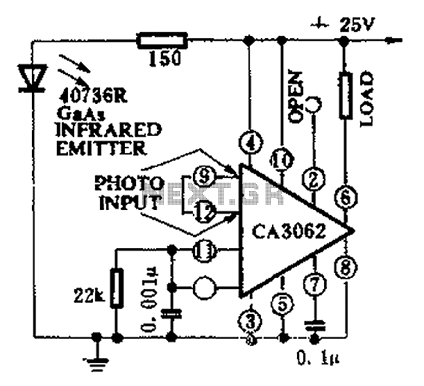
CA3062 is a combined photodetector and power amplifier that responds to the optical signal generated by the on/off output. The integrated circuit's transistor output saturation should be either on or off to prevent temperature rise in the silicon. When...
The TL494 controls a car's audio inverter power supply, which is a high-fidelity audio power supply designed for custom vehicles. It operates reliably without the need for adjustments according to the provided circuit diagram. The TL494 is a versatile integrated...