
Car and Motorcycle Battery Tester

The Car and Motorcycle Battery Tester Circuit is designed to assess the condition and charge level of lead-acid batteries commonly used in vehicles. This circuit can be particularly useful for campers who rely on battery-powered devices, ensuring that batteries are adequately charged before embarking on a trip.
The circuit typically consists of a microcontroller or an analog voltmeter, resistors, diodes, and a display unit. The microcontroller monitors the voltage levels of the battery and determines its state of charge. When the battery is connected to the tester, the circuit measures the voltage and displays it on an LCD or LED screen, indicating whether the battery is fully charged, partially charged, or needs recharging.
To build the circuit, a voltage divider may be employed to scale down the battery voltage to a level suitable for the microcontroller's analog-to-digital converter (ADC). This allows for accurate readings of the battery voltage. Additionally, protection diodes can be included to prevent reverse polarity connections, which could damage the circuit.
The tester circuit can also incorporate an audible alarm or LED indicators to provide immediate feedback on the battery's status. This feature is particularly beneficial in camping scenarios, where quick assessments of battery health are crucial for maintaining device functionality.
Ultimately, the Car and Motorcycle Battery Tester Circuit serves as a vital tool for outdoor enthusiasts, ensuring that their battery-powered devices remain operational throughout their adventures.Car and Motorcycle Battery Tester Circuit Going camping nowadays involves taking lots of electronic equipment whether for day to day running or for fun and entertainment. Most of the time a charged lead acid battery and a power.. 🔗 External reference
Related Circuits
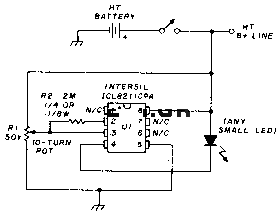
The precision voltage-monitor chip features a temperature-compensated voltage reference. Resistor R1 divides the battery voltage to align with the built-in reference voltage of IC1 (15 volts). When the voltage at pin 3 drops below 15 volts, pin 4 provides...
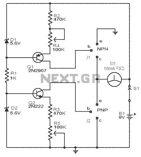
This circuit is a simple device for testing the hfe (current gain) of both PNP and NPN transistors, with the capability to measure hfe values as high as 1000. It operates using two constant current sources formed by transistors...
The car's small lamp and headlight can drain the battery if they are not turned off, leading to engine starting issues. A simple circuit, developed around 1980, can prevent this problem. It includes a series circuit with a diode...
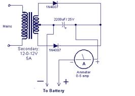
This design presents a circuit diagram for a straightforward battery charger capable of charging various types of 12V rechargeable batteries, including car batteries. The ammeter reading will indicate zero when the battery is fully charged. It is essential to...
I designed a simple sinewave generator based on a Analog Devices AD9832 chip. It will generate a sinewave from 0.005 to 12 MHz in 0.005 Hz steps. That's pretty good, and definitely good enough for me! But while waiting...
This is a Courtesy Light Extender for vehicles. It extends the ON time of the interior lights when a door is closed, allowing passengers to see where they are seated. The Courtesy Light Extender circuit is designed to enhance the...