
battery charger for 12v

The circuit diagram for the battery charger typically includes several key components: a transformer, a rectifier, a filter capacitor, an ammeter, and a voltage regulator. The transformer steps down the AC voltage from the mains supply to a lower AC voltage suitable for charging the battery. The rectifier, often a bridge rectifier configuration, converts the AC voltage to pulsating DC voltage.
Following the rectification process, a smoothing filter capacitor is employed to reduce the ripple in the output voltage, providing a more stable DC voltage to the battery. The ammeter is connected in series with the battery to monitor the charging current. When the battery approaches full charge, the current will decrease, eventually reaching zero, indicating that the charging process is complete.
A voltage regulator may also be included in the circuit to ensure that the output voltage does not exceed the battery's rated voltage, preventing overcharging, which can damage the battery. Additionally, it is crucial to implement reverse polarity protection using a diode to safeguard against incorrect connections, which can lead to circuit failure or battery damage.
In summary, this battery charger circuit is designed with essential components to ensure efficient charging of 12V batteries while incorporating safety features to protect both the charger and the battery from potential damage due to incorrect usage. Proper attention to component selection and circuit layout is vital to achieving optimal performance and reliability.This is a design of the circuit diagram of a simple and straight forward battery charger that can be used to charge all type of 12V rechargeable batteries including car batteries. For indicate when the battery is fully charged, the ammeter reading will be zero. For attention, it is always be careful to connect the charger to the battery in correct polarity. 🔗 External reference
Related Circuits
Application note on designing linear and switch-mode (switching DC-DC converter current source) battery charger applications that require external microcontrollers and related system-level issues for notebook computers. The application note provides guidance on the design of both linear and switching DC-DC...
This document presents the circuit diagram of an IC-controlled emergency light with a charger, which functions as a 12V to 220V AC inverter circuit. The primary features of this circuit include automatic activation of the light during mains failure...
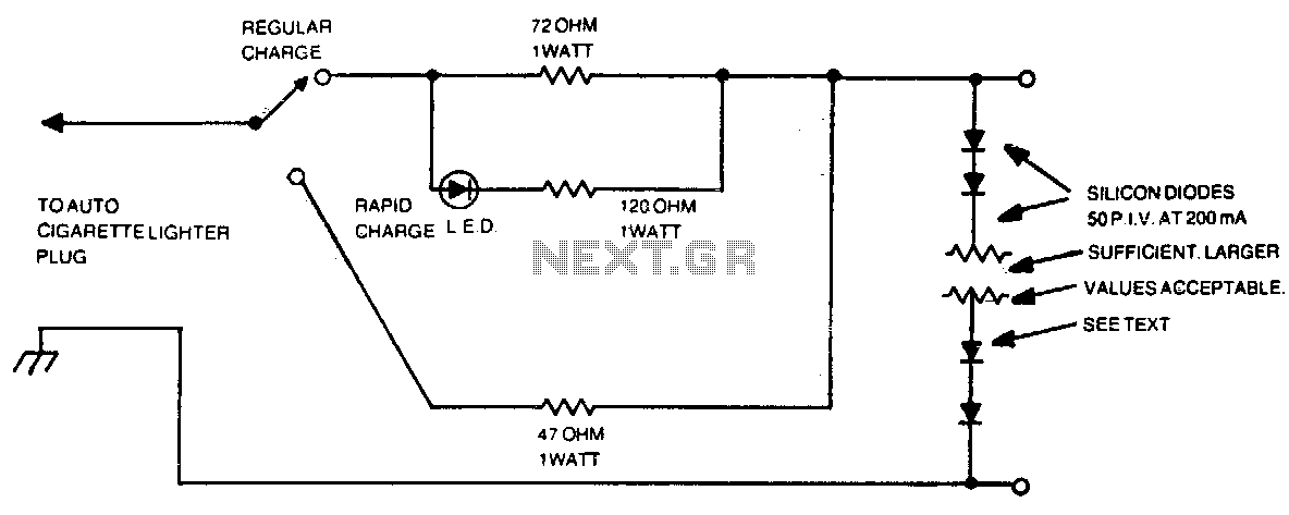
The number of silicon diodes across the output is determined by the voltage of the battery pack. Each diode is considered at 0 volts. For example, a 10-volt pack would require 10/0 = 157, or 16 diodes. In the context...
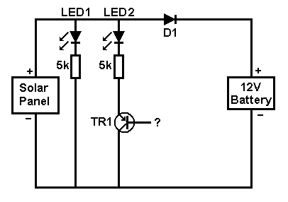
A small solar panel is used to maintain a 12V car battery. The panel provides approximately 75mA of current to the battery under full sunlight conditions. The described circuit employs a solar panel specifically designed for battery maintenance applications. The...
The Battery Good checker. When the button is pressed, the green LED will glow if the battery voltage is above the preset threshold. This version has a higher parts count than the Battery Low version, but a bonus is...
This document presents a straightforward and practical schematic for a 12V to 3V converter circuit. The output current of the circuit is approximately 1A. The 12V to 3V converter circuit is typically designed using a linear voltage regulator or a...