
car battery charger circuit

The circuit operates on a straightforward principle, relying on a direct connection to a power supply rather than incorporating additional power conversion elements. This design choice simplifies the circuit and reduces component count, making it easier to assemble and maintain. When connecting the circuit to a power supply, it is essential to ensure that the voltage and current ratings are compatible with the requirements of the charging circuit and the battery being used.
The output terminals are where the battery will be connected for charging. It is crucial to observe the polarity of the connections to prevent damage to the battery or the circuit. The inclusion of a "Start" switch (S1) allows for manual control over the charging process, providing the user with the ability to initiate charging at their discretion.
Monitoring the circuit during its initial operation is a critical step to ensure safety and functionality. Overcharging can lead to battery damage or reduced lifespan, so it is recommended to check the battery voltage and temperature periodically. If necessary, additional protective features such as a charging status indicator or an automatic cutoff mechanism can be integrated into the circuit to enhance safety and user experience. Overall, this circuit provides a practical solution for battery charging, with the flexibility to expand its capabilities as needed.The circuit was meant to be powered by a power supply, which is why there is no transformer, rectifier, or filter capacitors on the schematic. There is no reason why you cannot add these. To use the circuit, hook it up to a power supply/plug it in. Then, connect the battery to be charged to the output terminals. All you have to do now is push S1 ( the "Start" switch), and wait for the circuit to finish. The first time you use the circuit, you should check up on it every once and a while to make sure that it is working properly and the battery is not being over charged. 🔗 External reference
Related Circuits
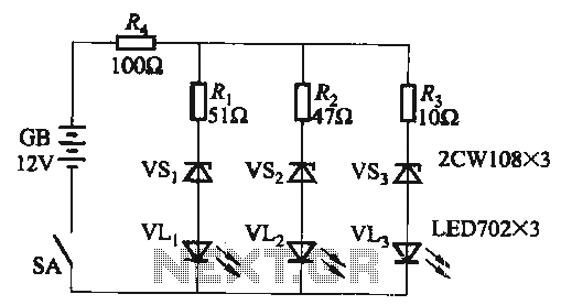
When the supply voltage falls below 10.2V, the yellow light-emitting diode (LED) VLi illuminates, indicating that the storage pool can no longer continue to discharge. Additionally, when the voltage exceeds 16.2V, the yellow, green, and red light-emitting diodes (LEDs)...
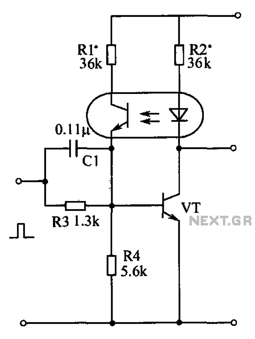
The bistable circuit and optocoupler transistor operate as illustrated in the accompanying figure. Initially, when the supply voltage is applied, the transistor VT is in the off state, resulting in a high output potential. Upon receiving a forward pulse...
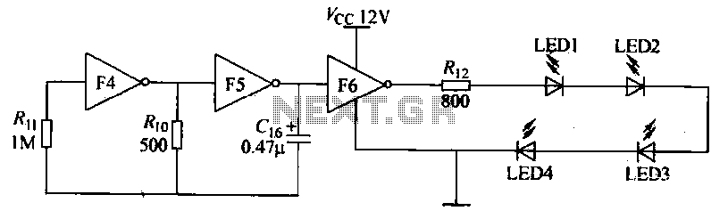
Gates F4, F5, and F6 together form a low-frequency oscillator that drives high-brightness light-emitting diode (LED) flashes. The light-emitting diodes may be arranged around the booth seat for decorative purposes. The automatic referral machine is used prior to operation...
This circuit is a wireless car alarm system composed of two modules: a transmitter and a receiver. It operates using FM radio waves and is compatible with vehicles that have a 6-12V DC power supply. If the vehicle's power...
The decision to use electric power was made due to its quieter operation, lack of odor, and ease of carrying the bike up a flight of stairs. The selected conversion kit is manufactured by Currie. Although factory service is...

This ultra wide range timer utilizes a 555 timer as its core component, along with two 4017 decade counters and a 4020 binary counter that function as frequency dividers, which can be selectively switched in and out. Additionally, the...