
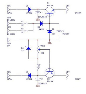
DC supply voltage the more limited indication circuit

The described circuit employs a voltage monitoring system that utilizes light-emitting diodes (LEDs) to provide visual indicators of the battery or storage pool voltage levels. The circuit is designed to operate within specific voltage thresholds to protect the storage pool from over-discharge and over-charge conditions.
At the lower voltage threshold of 10.2V, the activation of the yellow LED (VLi) serves as a warning signal, alerting users that the voltage has fallen below a critical level. This condition indicates that the storage pool's capacity is nearly depleted, and further discharge could lead to irreversible damage or reduced lifespan of the storage cells.
Conversely, when the voltage exceeds 16.2V, a combination of yellow (VLi), green (VL2), and red (VLa) LEDs illuminate. This multi-LED indication serves to inform the user that the voltage is in an overcharge condition. The red LED specifically emphasizes the urgency of the situation, prompting immediate action to either stop charging or to reduce the charging current to prevent potential damage to the storage pool.
In the voltage range between 10.2V and 16.2V, both the yellow and green LEDs are activated. This state indicates that the system is operating within a safe and acceptable voltage range, allowing for normal charging and discharging operations. The green LED typically signifies that the system is functioning properly and that the voltage level is stable.
The circuit can be implemented using a voltage divider to monitor the voltage level, coupled with a comparator circuit that triggers the appropriate LEDs based on the detected voltage. The use of resistors and possibly a microcontroller can enhance the precision of voltage detection and LED control, allowing for customizable thresholds and additional features such as alarm signals or communication with other system components.When the supply voltage drops below 10. 2V, the yellow light emitting diode VLi light, suggesting that storage pool can not continue to discharge. When the voltage exceeds 16. 2V, the yellow, green and red light-emitting diodes VLi ~ VLa are light, suggesting that must immediately stop charging or reduce the charging current. When the voltage is within 10.2-16. 2V, the yellow and green light-emitting diode VLi, VL2 light.
Related Circuits
The file being accessed no longer exists. It may have been renamed or removed from the archive. Navigation links are available on the left to browse the desired area of the archive. The connection is to cdn.preterhuman.net, which mirrors...
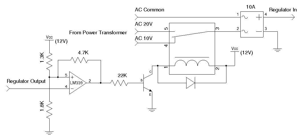
A used 250VA power transformer has been removed from equipment recently. The transformer features a dual 10V AC output along with several auxiliary voltage outputs. The 10V winding is rated for 10A, making it suitable for a high current...
DC fan control circuit for a power amplifier. It features a variable speed DC fan that operates based on the input signal. The speed of the fan's rotation is dependent on the amplitude of the input signal received from...
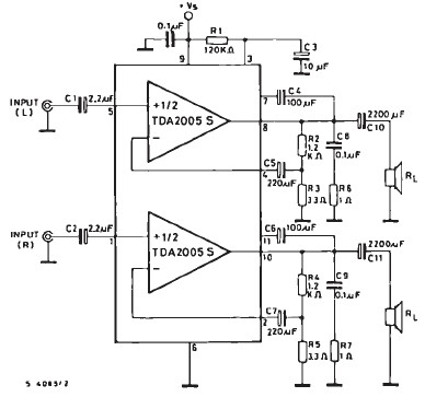
The TDA2005 car audio amplifier circuit is specifically designed for use in devices such as car radios, CD players, and similar equipment. This amplifier is based on the TDA2005 audio integrated circuit (IC), capable of delivering a maximum output...
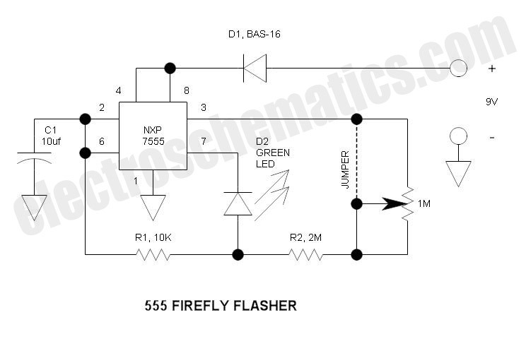
This circuit operates similarly to a standard 555 astable timer, with the distinction that the LED is integrated into the capacitor reset path. Consequently, when pin 7 discharges capacitor C1 to ground, a relatively high current flows through the...
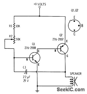
R2 controls the charging speed of capacitor C1. At a specific charge level, C1 triggers transistors Q1 and Q2, which release a 9-volt pulse. This pulse generates a clicking sound. The discharge process of the capacitor involves it charging...