
Car battery condition checker

The circuit design incorporates a 4081 CMOS quad two-input NAND gate, which is used for voltage comparison. The variable resistor, often referred to as a potentiometer, allows for fine-tuning of the reference voltage. When the ignition switch is engaged, the voltage is monitored; if it drops below the set threshold of 13 volts, the NAND gate outputs a low signal, activating the LED.
The LED serves as a visual indicator of the vehicle's electrical health. Under normal operating conditions, the LED will flicker occasionally, signaling that the system is functioning correctly. However, prolonged illumination of the LED suggests a problem, such as a failing alternator, battery issues, or excessive electrical load, necessitating further investigation.
The circuit may also include additional components such as resistors to limit current to the LED, ensuring its longevity. The configuration should be verified for proper connections and component ratings to prevent damage to the circuit. This setup is particularly useful in automotive applications where monitoring voltage levels is critical for maintaining the reliability of the vehicle's electrical system.This circuit uses an LED and 4081 CMOS integrated circuit. The variable resistor sets the voltage at which the LED turns on. Set the control so that the LED lights when the voltage from the car"s ignition switch drops below 13 volts The LED normally will light every now and then for a short period of time. But, if it stays on for very long, your electrical system is in trouble.
Related Circuits
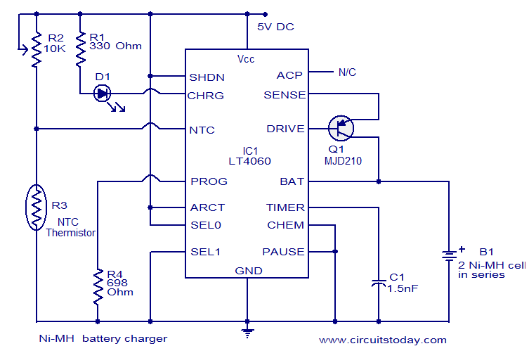
This circuit diagram represents a highly efficient Ni-MH battery charger utilizing the LT4060 integrated circuit from Linear Technologies. The circuit can also accommodate Ni-Cd batteries with minor modifications. To charge Ni-Cd batteries, the CHEM pin (pin 12) of the...
These controllers have an inhibit input and the effect of shorting this down to ground is to turn down the internal demand speed. So with the battery current limiter fitted, the internal demand speed can only ramp up to...
This circuit is relatively simple yet valuable, providing a high-quality interior light delay feature. This feature is commonly found in modern cars, although the automatic dimmer version is typically reserved for more expensive models. This circuit allows for the...
USB Battery Charger for Lithium Ion batteries using the LM3622 is a specialized charger circuit designed to operate with power sourced from a USB connection. The current consumption of the LM3622 is limited to 400mA by a resistor (R1),...
An LM556 dual oscillator/timer, U1, configured as a two-tone oscillator drives U2, a dual 4-watt amplifier. One of the oscillators, pins 1 to 6, contained in U1 produces the upper frequency signal of about 200 Hz, while the second...
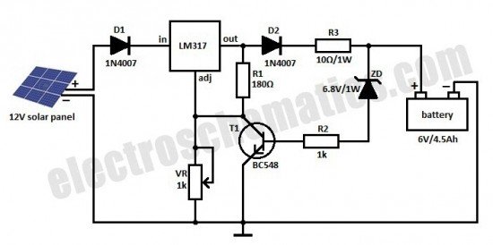
This is a solar charger circuit designed to charge Lead Acid or Ni-Cd batteries using solar energy. The circuit captures solar energy to charge the batteries. The solar charger circuit typically consists of several key components, including a solar panel,...