
Luxury Car Interior Light

The circuit employs a straightforward design that effectively enhances the interior lighting experience in vehicles lacking this feature. The relaxation oscillator, created with IC1.A, generates a square wave output, which is essential for the dimming effect. The triangular waveform generated at the inverting input is critical for the operation of the comparator in IC1.B, which manages the light's on/off state based on the door's position. The choice of components, particularly the op-amps and resistors, allows for flexibility in tuning the delay and dimming characteristics to suit specific preferences or requirements. This customization capability is particularly beneficial for users looking to retrofit older vehicles with modern conveniences. The circuit's low power consumption ensures that it does not adversely affect the vehicle's battery life, making it a practical addition for enhancing interior comfort and functionality. The design's compactness and ease of installation further contribute to its appeal, allowing for integration into various vehicle models without significant modifications. Overall, this circuit represents a valuable improvement for mid-range vehicles, providing a feature that enhances usability and comfort for drivers and passengers alike.This circuit is much more modest, but certainly still worth the effort. It provides a high quality interior light delay. This is a feature that is included as standard with most modern cars, although the version with an automatic dimmer is generally only found in the more expensive models. With this circuit it is possible to upgrade second hand an d mid-range models with an interior light delay that slowly dims after the door has been closed. The dimming of the light is implemented by means of pulse-width modulation. This requires a triangle wave oscillator and a comparator. Two opamps are generally required to generate a good triangle wave, but because the waveform doesn`t have to be accurate, we can make do with a single opamp. This results in the circuit around IC1. A, a relaxation oscillator supplying a square wave output. The voltage at the inverting input has more of a triangular shape. This signal can be used as long as we do not put too much of a load on it. The high impedance input of IC1. B certainly won`t cause problems in this respect. This opamp is used as a comparator and compares the voltage of the triangular wave with that across the door switch.
When the door is open, the switch closes and creates a short to the chassis of the car. The output of the opamp will then be high, causing T1 to conduct and the interior light will turn on. When the door is closed the light will continue to burn at full strength until the voltage across C2 reaches the lower side of the triangle wave (about 5 V).
The comparator will now switch its output at the same rate of the triangle wave (about 500 Hz), with a slowly reducing pulse width, which results in a slowly reducing brightness of the interior light. R8 and C3 protect the circuit from voltage spikes that may be induced by the fast switching of the light.
The delay and dimming time can be adjusted with R6 and C2. Smaller values result in shorter times. You can vary the dimming time on its own by adjusting R1, as this changes the amplitude of the triangle wave across C1. R7 limits the discharge current of C2; if this were too big, it would considerably reduce the lifespan of the capacitor.
There is no need to worry about reducing the life of the car battery. The circuit consumes just 350 µA when the lamp is off and a TLC272 is used for the dual opamp. A TL082 will take about 1 mA. These values won`t discharge a normal car battery very quickly; the self-discharge is probably many times higher. It is also possible to use an LM358, TL072 or TL062 for IC1. R8 then needs to have a value between 47 and 100 . Since T1 is always either fully on or fully off, hardly any heat is generated. At a current of 2 A the voltage drop across the transistor is about 100 mV, giving rise to a dissipation of 200 mW.
This is such a small amount that no heatsink is required. The whole circuit can therefore remain very compact and should be easily fitted in the car, behind the fabric of the roof for example. 🔗 External reference
Related Circuits
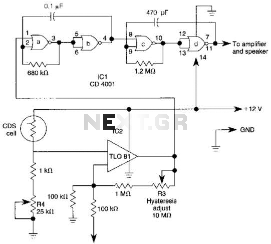
The TL081 is utilized as a comparator within a Wheatstone bridge circuit. When the resistance of the CDS cell decreases due to light exposure, the output from IC2 prompts the low-frequency oscillators (a) and (b) to produce a 10-Hz...

This simple circuit drives six LEDs in a "Knightrider scanner mode." Power consumption primarily depends on the type of LEDs used, particularly when utilizing a 7555 (the CMOS version of the 555 timer). The circuit is designed to create a...
The optically-controlled circuit plays a crucial role in urban street lighting and corridor illumination. By utilizing this circuit, lighting lamps can be automatically turned on and off based on ambient light levels, thereby reducing the need for manual control,...
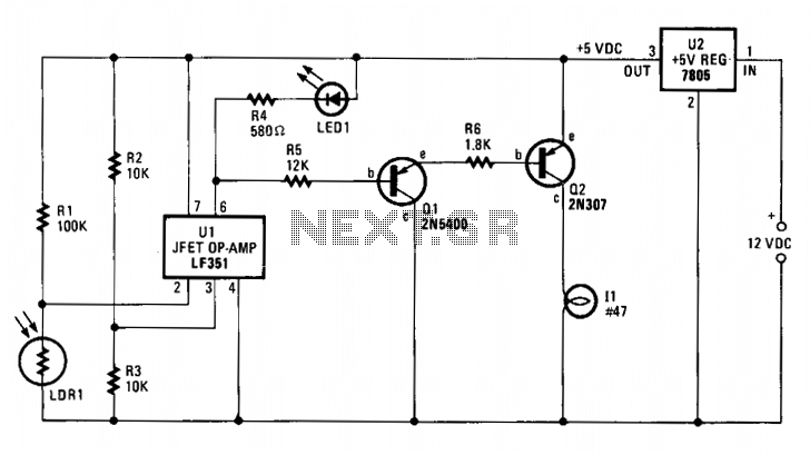
The integrated circuit U1, which can be an LF351 or a 741 operational amplifier, functions as a comparator to regulate lighting. Resistors R2 and R3 establish a reference voltage of approximately 2.5 volts at pin 3 of U1. When...
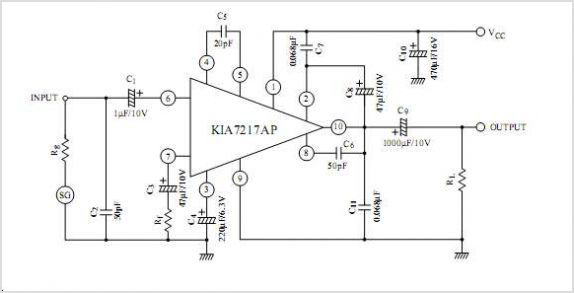
The UTC L2572 is a wideband PLL FM demodulator designed primarily for use in satellite tuners. It incorporates all essential components, except for the loop feedback elements, to create a complete PLL system capable of operating at frequencies up...
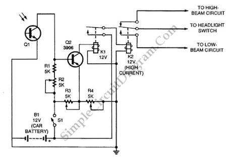
Automatic headlight dimmer circuit diagram for a car's headlight. This circuit ensures maximum brightness for optimal visibility while automatically switching when necessary. The automatic headlight dimmer circuit is designed to enhance driving safety by adjusting the brightness of the vehicle's...