
Car battery tester circuit

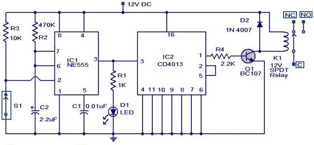
The automatic wiper control circuit is designed to enhance driving safety and comfort by allowing the driver to customize the wiper operation based on environmental conditions. The astable multivibrator configuration of the 555 IC generates a continuous square wave output, which is essential for controlling the timing of the wiper motor. By adjusting the resistance of R2, the duty cycle of the output waveform can be varied, effectively changing the duration for which the wiper motor is activated.
In this circuit, the 555 timer is configured in astable mode, where it oscillates between high and low states. The frequency of this oscillation is determined by the values of resistors R1 and R2, as well as the capacitor C1. The relationship between these components can be expressed using the formula for the frequency of the oscillation. The output from pin 3 of the 555 timer drives a relay or a transistor connected to the wiper motor, allowing it to operate intermittently rather than continuously.
The power supply for this circuit is specified at 12V, which is typical for automotive applications. This ensures compatibility with the vehicle's electrical system. The potentiometer R2 should be rated appropriately to handle the voltage and current levels in the circuit, and it should be mounted in a location that is easily accessible to the driver.
In summary, this automatic wiper control circuit offers an economical and effective solution for adjusting wiper speeds, improving the overall driving experience during adverse weather conditions. By allowing for manual control over the wiper operation, the driver can ensure optimal visibility without the distraction of incessant wiping.In rainy seasons, it is very annoying that wiper of your car wiping instantly all the time. Have you ever think of speed control of the wiper. There are wiper control modules available on the market but most of them are costly. So here is an automatic wiper control circuit which enables you to control your wiper sweep rates from 1 second to 10 sec ond. The heart of this circuit is an astable multivibrator using 555 Ic. We actually change the duty cycle of the square wave to obtain different sweep rates to control the wiper. The output pin 3 of the IC remains high for a time period set by R2. During this time the wiper motor will sweep at rates. The power supply to this wiper control circuit should be 12V. fit the potentiometer R2 anywhere on the dashboard of your vehicle and control the sweep rates according to the intensity of the rain.
🔗 External reference
Related Circuits
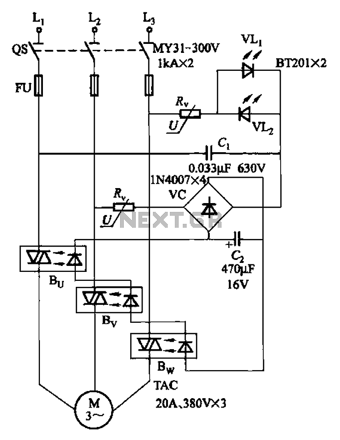
The circuit depicted in Figure 3-93 is integrated with an optical phase sequence protection relay. The circuit in question is designed to provide phase sequence protection using an optical relay mechanism. Optical phase sequence protection relays are crucial in applications...
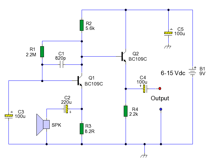
This circuit enables the use of an inexpensive loudspeaker as a microphone. Sound waves that reach the speaker cone create fluctuations in the voice coil. The movement of the voice coil within the speaker's magnetic field generates a small...
This weblog discusses electronic circuit schematics, PCB design, DIY kits, and electronic project diagrams. The circuit diagram presented is for a magnetic proximity switch, which has numerous applications across various fields. The circuit utilizes a magnetic reed switch (S1)...
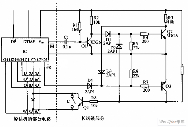
A simplified long-distance call lock is illustrated in the accompanying image. This device is designed to prevent long-distance calls while maintaining the original functionality of the phone. Although it consumes power, it exhibits excellent compatibility. When switch K is...
The refrigerator turned on, causing the lights to brighten. Initially, it seemed like an illusion, but after observing multiple cycles, the phenomenon persisted. When the microwave was activated, the lights dimmed. The refrigerator's operation appeared to influence the brightness...
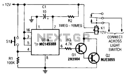
A normally open pushbutton switch (SI) provides a positive input pulse to pin 4 of U1, activating the integrated circuit (IC). The output from U1 at pin 6 delivers base-drive current to a Darlington pair consisting of Q1 and...