
Simplified Long-Distance Call LockCircuit

The long-distance call lock circuit is an essential tool for managing telecommunication expenses, particularly in environments where unauthorized long-distance calls may occur. The circuit typically incorporates a relay or a transistor switch that is controlled by the position of switch K.
When switch K is in the designated position, it engages a blocking mechanism that interrupts the dialing process for long-distance calls. The circuit is designed to detect the dialing of the number '0', which is often the prefix for long-distance calls in many telecommunication systems. The blocking mechanism can be implemented using a combination of resistors, capacitors, and diodes that work together to create a control signal to the relay or transistor.
The power consumption of the circuit is a critical consideration, as it must be low enough to avoid excessive energy costs while still providing reliable operation. The compatibility of the device with various telephone systems is facilitated through the use of standard components that can be easily integrated into existing phone lines without requiring significant modifications.
In summary, this long-distance call lock circuit effectively prevents unauthorized long-distance dialing while preserving the basic functionality of the telephone system, making it a valuable addition to any telecommunication setup.Simplified long-distance call lock is shown in the above picture. The lock can lock out the long-distance call without affecting the original function. It ispower-consuming, but it has very good compatibility. If switch K is placed as the picture shows, first dial the number 0,, and you ll find the 0 can not be dialed and the long-distance call can not.. 🔗 External reference
Related Circuits
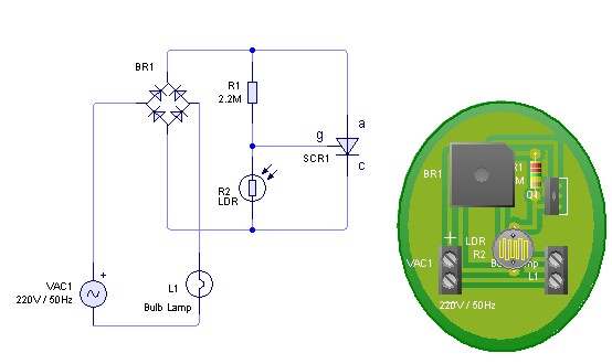
Adjust the value of R1 to achieve optimal performance of the LDR sensor. If, in practice, a resistance of 2.2 MΩ still activates the lamp, it is possible to increase the value of R1 to a larger resistance of...
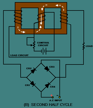
The power used for realignment is considered a loss in the context of the overall circuit. Due to the hysteresis loss in the saturable-core reactor, the power gain is relatively low. Adding a rectifier to the load circuit can...
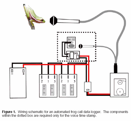
Automated frog call data loggers have been effectively utilized to gather information on: (1) species presence during sampling, enabling the reliable recording of species that may be overlooked due to time constraints; (2) life history and phenology details, such...
This caller ID circuit utilizes the Motorola MG145447 IC chip. The service must be available from your local phone company for this circuit to function properly. The caller ID circuit based on the Motorola MG145447 IC chip is designed to...
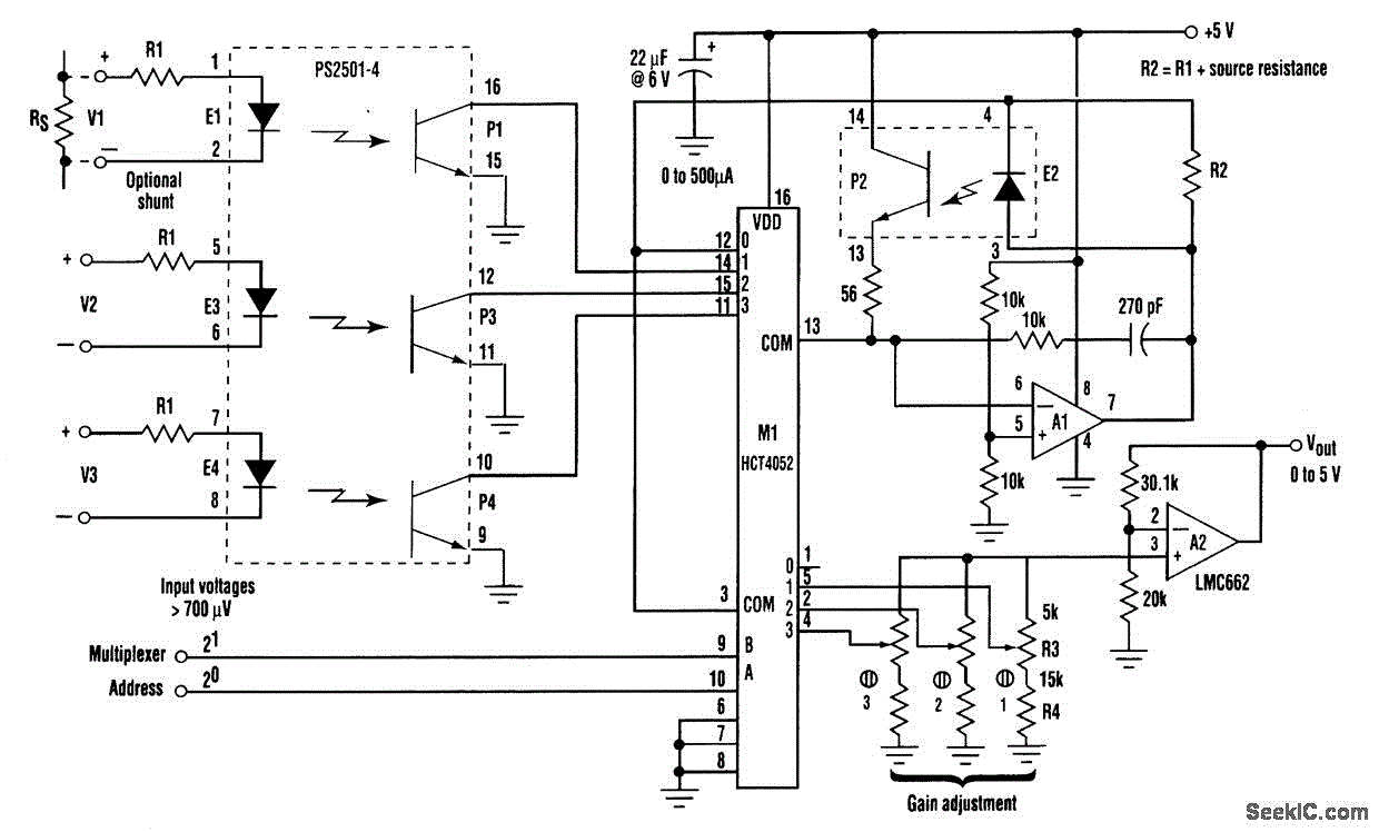
The circuit provides three channels of optically isolated input suitable for various precision signal-acquisition applications. It operates using a single 15-V power rail with a ground common to the analog-to-digital converter. The multiplexer functions through a standard quad-channel optoisolator...
This is an image Schematic. No Description available. The provided input indicates that there is an image schematic without any accompanying descriptive details. In the absence of specific schematics or circuit details, it is essential to consider the typical...