
Car Boot Light Warning

The schematic circuit described incorporates several key components and functionalities designed to prevent battery drain due to an ajar boot lid. The mercury tilt switch acts as a primary sensor, detecting the position of the boot lid. When the boot is closed, the switch opens, interrupting the circuit and ensuring that the alarm system is inactive. Conversely, if the lid is left open, the switch closes, allowing current to flow through the circuit.
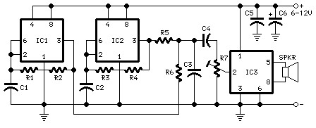
The dual CMOS timer IC (7556) plays a crucial role in timing the alarm activation. It is configured in a monostable mode where the first timer (IC1a) is responsible for resetting the second timer (IC1b) after a predetermined duration. The capacitors C1 and C2 are essential for establishing the timing intervals. The values of these capacitors, along with the resistance of R6, can be adjusted to fine-tune the timing characteristics of the alarm system.
The alarm itself is activated by the output of IC1b, which drives a buzzer designed for DC operation. This buzzer emits an audible signal when triggered, alerting the user to the condition of the boot lid. The design ensures that the alarm does not sound continuously for an extended period, providing a reasonable timeout that allows for user intervention without causing undue annoyance.
For practical implementation, it is vital to ensure that the components selected meet the specifications required for automotive applications, particularly in terms of temperature resilience and vibration tolerance. The choice of tantalum capacitors is specifically highlighted due to their reliability and performance in such environments. Proper layout and connections in the circuit design will also contribute to the overall functionality and durability of the system, ensuring that it operates effectively over the lifespan of the vehicle.On many cars, the boot light will not go out until the lid is properly closed. It is all too easy when unloading the car, to leave the lid ajar. If you are unlucky and the car remains unused for some time, the next time you try to start it, the lamp will have drained the battery and you will no doubt utter a few appropriate words. The circuit described here will give a warning of just such a situation. A mercury tilt switch is mounted in the boot so that as the lid is closed, its contacts close before the lid is completely shut. The supply for the circuit comes from the switched 12 V to the boot lamp and through the mercury switch.
When the lid is properly closed, the boot lamp will go out and the supply to the circuit will go to zero. If however the lid is left ajar, the lamp will be on and the mercury switch will close the circuit. After 5 seconds, the alarm will start to sound, and unless the lid is shut, it will continue for 1 minute to remind you to close the boot properly.
The 1-minute operating period will ensure that the alarm does not sound continuously if you are, for example, transporting bulky items and the boot will not fully close. The circuit consists of a dual CMOS timer type 7556 (the bipolar 556 version is unsuitable for this application).
When power is applied to the circuit (i. e. the boot lid is ajar) tantalum capacitors C1 and C2 will ensure that the outputs of the timers are high. After approximately 5 seconds, when the voltage across C2 rises to 2/3 of the supply voltage, timer IC1b will be triggered and its output will go low thereby causing the alarm to sound.
Meanwhile the voltage across C1 is rising much more slowly and after approximately 1 minute, it will have reached 2/3 of the supply voltage. IC1a will now trigger and this will reset IC1b. The alarm will be turned off. IC1a will remain in this state until the boot lid is either closed or opened wider at which point C1 and C2 will be discharged through R6 and the circuit will be ready to start again.
To calculate the period of the timers use the formula: t = 1. 1RC Please note that the capacitor type used in the circuit should be tantalum or electrolytic with a solid electrolyte. The buzzer must be a type suitable for use at D. C. (i. e. one with a built in driver). 🔗 External reference
Related Circuits
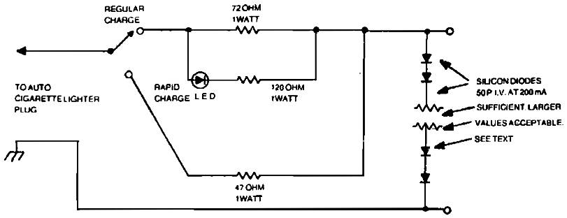
Car charger for NiCd battery packs power supply. This is a car NiCd battery charger circuit that can charge any Ni-Cd battery between 4.8 and 4.4 volts from a classic 12 volts car battery. The charging current is constant...
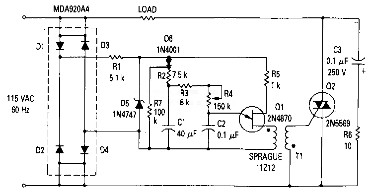
The zener diode maintains a constant voltage of 20 V for the unijunction transistor Q1, except at the end of each half-cycle of the input when the line voltage drops to zero. Initially, the voltage across capacitor C1 is...
This simple circuit drives six LEDs in a Knight Rider scanner mode. Power consumption primarily depends on the type of LEDs used, especially when utilizing a 7555 (555 CMOS version). The Knight Rider scanner circuit is designed to create a...
Nowadays, a switch-off delay for vehicle interior lighting is a standard feature. However, certain models with minimal settings or older vehicles leave users in the dark as soon as they enter and close the door. This situation calls for...
The following diagram is the schematic diagram for a car horn circuit, which can be utilized for car modifications. Components List: R1 = 68K, R2 = 2K2, R3 = 56K, R4 = 3K3, R5, R6 = 4K7, R7 =...
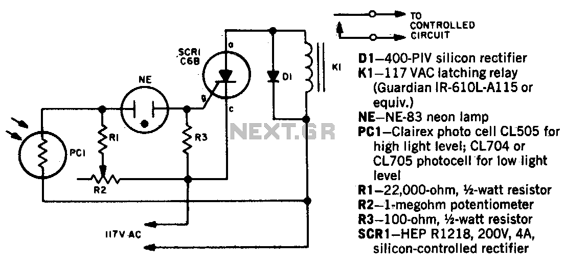
When a beam of light strikes the photocell, the voltage across the neon lamp NE-1 rises sharply. NE-1 turns on and triggers the SCR. K1 is an impulse relay whose contacts remain in position even after the coil current...