
Car Door Keypad Electronic

The Car Door Keypad Electronic Circuit is designed to enhance vehicle security by providing a user-friendly interface for locking and unlocking car doors. This circuit employs the MC68HC908AZ60A microcontroller, which is known for its efficiency and compact design, making it ideal for automotive applications.
The circuit typically consists of a keypad, which allows the user to input a security code. The microcontroller processes the input signals from the keypad and compares them to a pre-stored code in its memory. If the entered code matches the stored code, the microcontroller activates a relay or an electronic lock mechanism to unlock the car doors.
The schematic may include additional components such as resistors for pull-up or pull-down configurations, capacitors for noise filtering, and diodes for protection against reverse polarity. Power supply considerations are also crucial; the circuit should be designed to operate within the vehicle's standard voltage range, typically 12V.
In terms of layout, the circuit should minimize the length of connections to reduce electromagnetic interference, and components should be arranged to facilitate easy troubleshooting and maintenance. The use of a lower pin-count design not only reduces the overall cost of the circuit but also simplifies the PCB layout, allowing for a more compact design that can be easily integrated into the vehicle's existing systems.
Overall, this Car Door Keypad Electronic Circuit offers a reliable and efficient solution for vehicle access control, combining functionality with cost-effectiveness.The following circuit shows about Car Door Keypad Electronic Circuit Diagram. Features: lower pin-count lower cost device, uses an MC68HC908AZ60A, .. 🔗 External reference
Related Circuits

The battery should charge up to 14 volts. A reading of 10.7 volts indicates that one cell is shorted. A good way to diagnose this further is to look at the water level in the cells. The shorted cell...
This project is built on the third section of the PC board, identified by "SIREN" and "Project 5." You will notice the similarity between this circuit and the LED FLASHER circuit from project 2. The only differences are the...

T-121 temperature sensor electronic thermometer circuit diagram shown below The T-121 temperature sensor circuit is designed to measure and display temperature readings accurately. The circuit typically consists of a temperature sensor, such as the T-121, which converts temperature variations into...

The TL494 controls a car's audio inverter power supply, which is a high-fidelity audio power supply designed for custom vehicles. It operates reliably without the need for adjustments according to the provided circuit diagram. The TL494 is a versatile integrated...

A simple electronic multimeter offers an affordable alternative for hobbyists deterred by the high cost of conventional multimeters. This device is designed to measure three ranges: (i) 0-15V, (ii) 0-15mA, and (iii) 0-150mA, with the possibility of extending the...
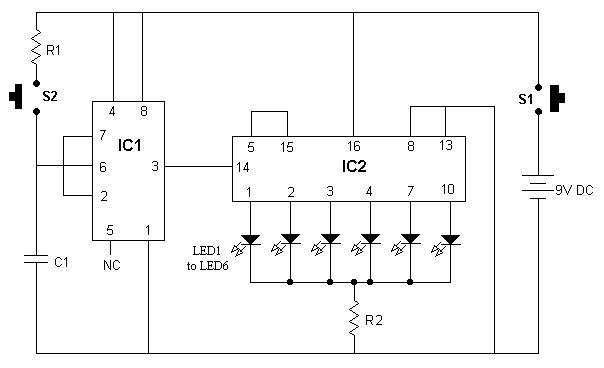
It is advisable to enclose this circuit in a box and label each LED with numbers from 1 to 6. When switch S1 is momentarily pressed, one of the six LEDs will illuminate, with the number corresponding to the...