
T-121 Temperature sensor circuit diagram (electronic thermometer)
")
The T-121 temperature sensor circuit is designed to measure and display temperature readings accurately. The circuit typically consists of a temperature sensor, such as the T-121, which converts temperature variations into an electrical signal. This signal is then processed by an analog-to-digital converter (ADC) to provide a digital output that can be displayed on a digital readout, such as an LCD or LED display.
The T-121 sensor operates within a specified temperature range and outputs a voltage that is proportional to the temperature. The circuit includes essential components such as resistors for biasing, capacitors for filtering, and operational amplifiers for signal conditioning. The ADC is crucial for converting the analog signal from the sensor into a digital format that can be easily read and interpreted.
Power supply considerations are also vital for the operation of this circuit. A stable voltage source is required to ensure accurate readings. Additionally, the circuit may include a microcontroller to manage the data processing and display functions, allowing for features such as temperature logging or calibration adjustments.
Overall, the T-121 temperature sensor circuit is a fundamental design in electronic thermometry, providing reliable temperature measurements for various applications, including environmental monitoring and industrial processes. Proper layout and component selection are critical to achieving optimal performance and accuracy in temperature readings.T-121 temperature sensor electronic thermometer circuit diagram shown below
Related Circuits

When the switch is opened, the timer generates an approximate 1-second clock signal, decrementing the counter until it reaches a count of zero. Upon reaching zero, the carry-out signal at pin 7 of the counter goes low, energizing a...
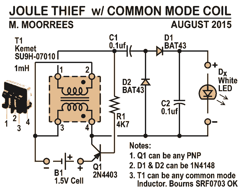
Like all joule thieves, this circuit boosts the voltage from a single 1.5V dry cell battery high enough to illuminate ultrabright GaN blue, green, or white LEDs. Instead of requiring a custom coil, it utilizes an off-the-shelf standard Kemet...

The main component is the LG26 one-inch screens integrated with the FSP107-2PS01 two-in-one electrical power package, which utilizes a direct drive CCFL modulator tube. This setup is compatible with screens from other manufacturers, such as Samsung and AU, but...

This circuit demonstrates a method to enhance the power capability of a drive system for audio speakers. Two HA-2542 amplifiers are utilized to operate on half cycles only, significantly increasing their power handling capacity. Bridging the speaker, as illustrated,...
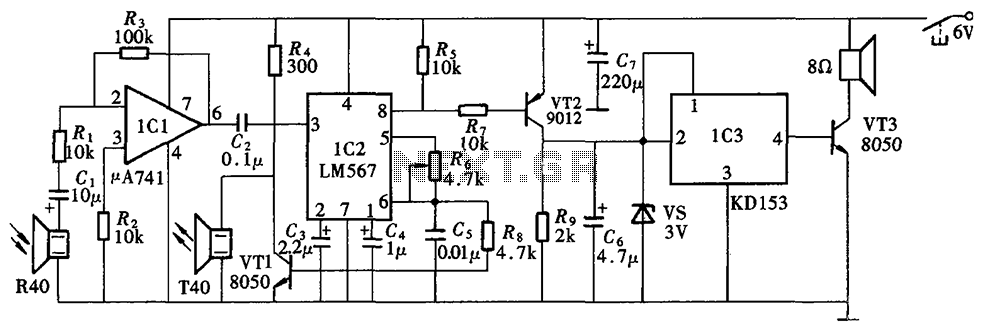
The Blind Pathfinder circuit primarily consists of the A741 operational amplifier, LM567 phase-locked loop, KD153 transistor, 8050 transistor, 9012 transistor, and various other components. The Blind Pathfinder circuit is designed to assist in navigation and obstacle detection, typically utilized in...
The following circuit illustrates the use of the AD8531 integrated circuit for the automatic control of LCD panel backlighting. Features include the ability to compensate for aging effects. The AD8531 is a precision operational amplifier that is well-suited for applications...