
Car Horn

The car horn circuit schematic serves as a guide for automotive enthusiasts looking to modify or enhance their vehicle's horn system. The circuit consists of various resistors, capacitors, and a potentiometer, each playing a critical role in the operation of the horn.
The resistors, designated as R1, R2, R3, R4, R5, R6, and R7, are used to set the biasing conditions and control the current flow within the circuit. Resistor R1, with a value of 68K, helps in limiting the current to protect sensitive components. R2 at 2K2 and R3 at 56K are used for voltage division and signal conditioning, while R4 at 3K3 and the pair of R5 and R6 at 4K7 each help in controlling the overall gain of the circuit. R7, a 10K potentiometer, provides the ability to adjust the output level, allowing for customization of the horn's sound intensity.
The capacitors, labeled C1 through C6, are crucial for filtering and smoothing the signal. C1 and C2, both rated at 22nF, are used for high-frequency noise filtering, ensuring that the horn operates smoothly without unwanted interference. Capacitors C3 and C5, rated at 100nF, serve a similar purpose but are tailored for different sections of the circuit to stabilize voltage levels. C4, with a value of 1nF, is likely used for decoupling purposes, while C6, also at 22nF, may serve as a coupling capacitor to block DC voltage while allowing AC signals to pass through.
This schematic can be implemented as part of a broader modification project, enhancing the auditory signaling capabilities of a vehicle. Proper assembly and adherence to the specified component values are essential for optimal performance. Additionally, careful attention should be paid to the power supply requirements and the integration of this circuit with existing automotive systems to ensure reliable operation.The following diagram is the schematic diagram fo Car Horn, you may try this circuit for your car modification Components List: R1 = 68K R2 = 2K2 R3 = 56K R4 = 3K3 R5,R6 = 4K7 R7 = 10K Pot/trimpot C1,C2 = 22nF C3,C5 = 100nF C4 = 1nF C6 = 22.. 🔗 External reference
Related Circuits
A car battery deteriorates in use, and its life seldom exceeds four years. When new, its voltage may drop to only 2V while cranking the engine. A car battery, typically a lead-acid type, is essential for providing the necessary electrical...
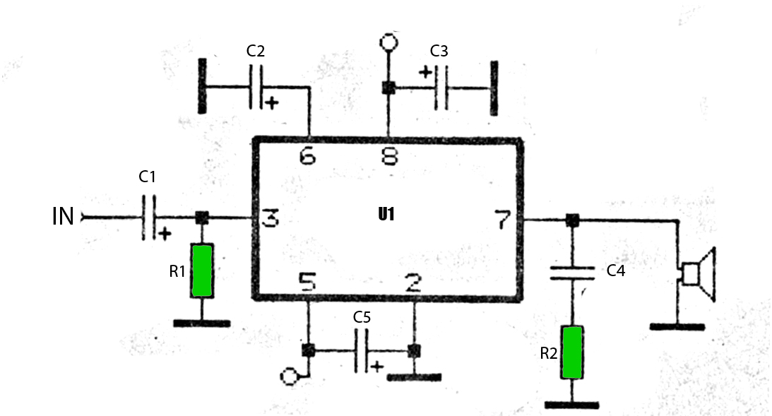
The car power amplifier utilizes the SI1050GL integrated circuit (IC) as the primary amplification component. It delivers an output power of 50 Watts at an 8-ohm mono impedance. The amplifier operates with a DC voltage of up to 25...
The brake lights of the automobile activate this circuit intermittently. This prevents unnecessary alarm activation when it is not required. Although this is an older circuit originally published in Popular Electronics Magazine, it remains effective today. The described circuit utilizes...
Most cars do not have delayed interior lights. The circuit presented can rectify this issue by gradually switching the interior lights of a car on and off. This feature facilitates tasks such as locating the ignition keyhole after the...

This simple circuit consists of a transformer, two diodes, a capacitor, and an ammeter. To charge a battery, connect the positive and negative terminals of the circuit to the corresponding terminals of the battery. When the battery is not...
After a year of observing and admiring various projects, a decision was made to create a personal project. The project aims to design an electronic circuit that incorporates various components to achieve a specific functionality. The schematic will typically include...