
DIY Circuit Car Battery Charger

The circuit operates by utilizing the transformer to step down the AC voltage from the mains supply to a lower voltage suitable for charging the battery. The two diodes are configured in a bridge rectifier arrangement, allowing for full-wave rectification of the AC voltage. This conversion is essential for providing a steady DC output to the battery.
The capacitor serves to smooth out the rectified voltage, reducing ripple and providing a more stable charging voltage to the battery. This smoothing effect is crucial for the longevity of the battery, as it helps prevent over-voltage conditions that can lead to damage.
The ammeter is connected in series with the battery and serves as an indicator of the charging current. During the charging process, the ammeter will display a current of 1-3 amps, indicating that the battery is being charged. As the battery reaches its full charge state, the charging current will decrease, eventually dropping to zero or close to zero. This drop in current signifies that the battery is fully charged and should be disconnected from the charger to prevent overcharging, which could lead to battery damage or reduced lifespan.
Overall, this circuit is a straightforward and effective solution for charging batteries, providing essential indicators and protections to ensure safe and efficient operation.This very simple circuit uses a transformer, two diodes, a capacitor and an ammeter. To charge a battery just connect the + and terminals of the circuit to the corresponding terminals of the battery. When the battery is not charged, the ammeter reading shows 1-3 amps. When the battery is fully charged the ammeter reads Zero or nearly zero, af ter which the battery should be removed from the charger. 🔗 External reference
Related Circuits
The circuit can be constructed using a pair of twin-T oscillators, with the Q factor adjusted to the threshold of oscillation, allowing them to resonate like a bell when activated by a voltage pulse. Each twin-T oscillator is designated...
This is a 100 Watt inverter circuit designed with a minimal number of components. The circuit utilizes the CD4047 integrated circuit from Texas Instruments to generate 100 Hz pulses, and it employs four 2N3055 transistors to drive the load....
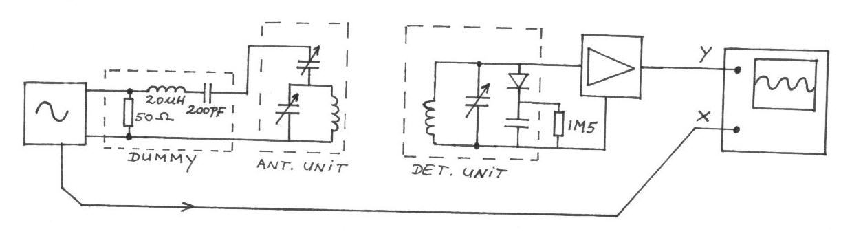
The frequency remains constant, oscillating between two predetermined values. On the oscilloscope display, a frequency spectrum is observed, showcasing the response curves of the two circuits. The input voltage of the receiver is 0.1 Volt peak-to-peak, while the voltage...
Most cars do not have delayed interior lights. The circuit presented can rectify this issue by gradually switching the interior lights of a car on and off. This feature facilitates tasks such as locating the ignition keyhole after the...
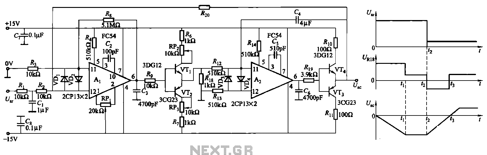
The ZKJ-S-type buffer controller circuit is designed for motor starting slip control. This buffer controller is composed of two operational amplifiers, Ai and Az. The operational amplifier Ai functions as a speed amplifier that saturates, while Az acts as...
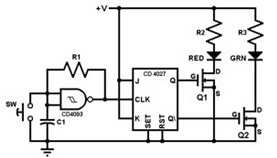
This project involves constructing a coin toss circuit that comprises three main sections: a square-wave oscillator, a JK flip-flop, and two LEDs (one red and one green). The circuit utilizes CMOS digital integrated circuits (ICs) and MOSFET transistors. The...