
car improvement automatic direction indicators

The operation of direction indicators, commonly known as turn signals, is crucial for safe driving, especially on high-speed roadways such as motorways. The direction indicator system consists of several key components: the indicator switch, the flasher unit, the bulb or LED indicators, and the vehicle's wiring harness.
The indicator switch is usually located on the steering column and is designed to be easily accessible to the driver. When the driver intends to change lanes, they activate the switch, which sends a signal to the flasher unit. The flasher unit is responsible for controlling the on-and-off blinking of the indicator lights, providing a visual cue to other drivers.
In modern vehicles, LED indicators are commonly used due to their energy efficiency and longer lifespan compared to traditional incandescent bulbs. The circuit design for the indicator system includes a relay that helps manage the current flow to the lights, ensuring they operate correctly without drawing excessive power from the vehicle's electrical system.
The wiring harness connects all components of the indicator system, routing power from the vehicle's battery to the flasher unit and the indicator lights. Proper insulation and protection of the wiring are essential to prevent short circuits and ensure reliable operation, especially in environments exposed to moisture and temperature variations.
In summary, the direction indicator system is a vital safety feature in vehicles, enhancing communication between drivers and promoting safer lane changes on motorways. Understanding the components and operation of this system is essential for effective vehicle maintenance and troubleshooting.As I often drive on motorways, I always and frequently use the direction indicators in order to show the lane change. I normally did this by holding a .. 🔗 External reference
Related Circuits
A simple but useful circuit for all who have problems with parking a car in spaces without good visibility. The electric circuit appears in picture 1. It is constituted by the IC1 and components around it. When the car...
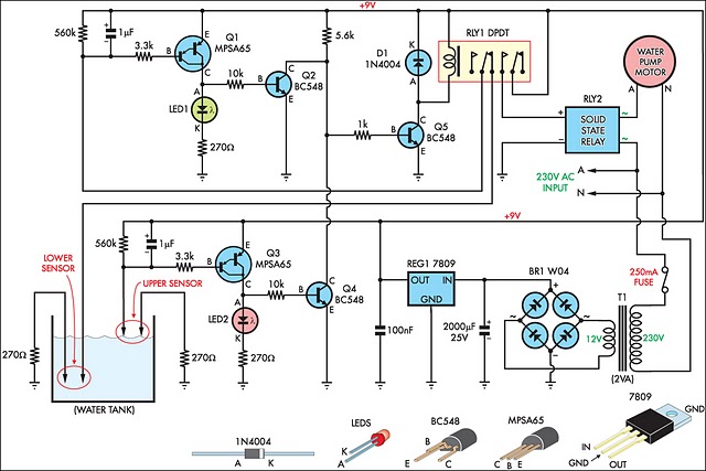
This circuit is designed to efficiently fill a header tank for a reticulated water supply on a farm. It supplies eight troughs located in various paddocks where water scarcity can have severe consequences for livestock. Previously, the tank was...
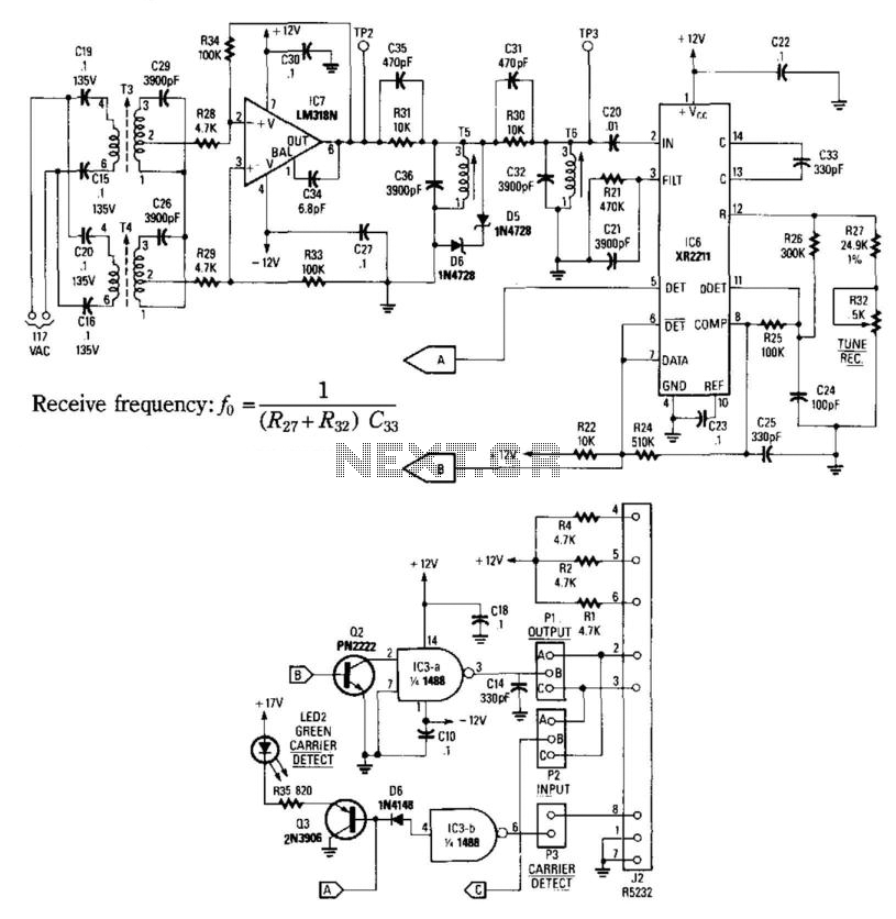
This receiver consists of an input network, amplifier IC7, FSK PLL detector IC8, and output amplifier/interface circuits Q2, Q3, IC3A, and IC3B, which include a 1488 Quad RS232 line driver for the carrier-current signal. The tuned amplifier IC7 amplifies...
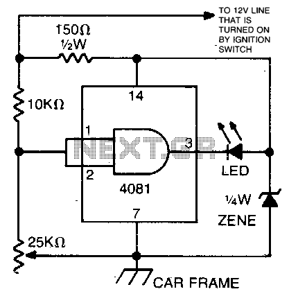
This circuit utilizes an LED and a 4081 CMOS integrated circuit. A variable resistor is employed to adjust the voltage threshold at which the LED activates. The control should be set so that the LED illuminates when the voltage...
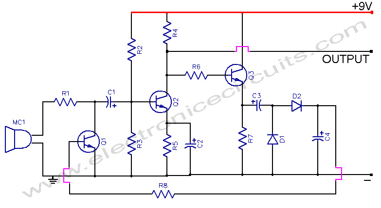
This microphone preamplifier incorporates automatic gain control, which keeps the output level fairly constant over a wide range of input. The microphone preamplifier is designed to enhance the audio signal from a microphone while maintaining a consistent output level. The...
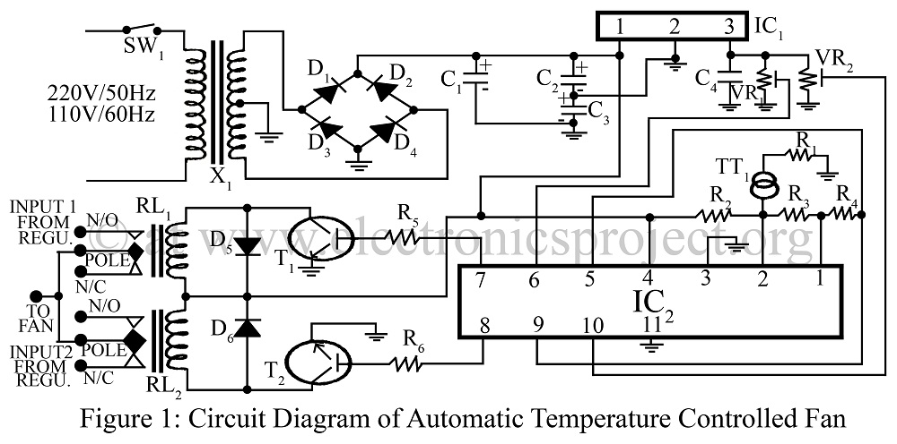
An automatic temperature-controlled fan regulates the fan speed based on temperature variations using the temperature transducer AD590 and an op-amp LM324 circuit diagram. The automatic temperature-controlled fan circuit utilizes the AD590 temperature transducer, which provides an output voltage that is...