
Car Parking Sensor Circuit Schematic Free With Explanation

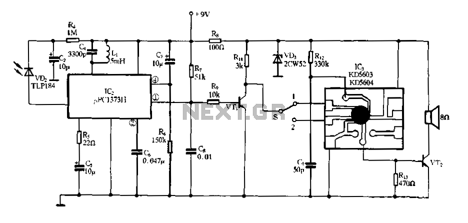
The circuit operates by utilizing infrared light to detect the proximity of objects, specifically the wall of a garage when parking. The core of the system is an oscillator circuit formed by IC1, which generates a series of pulses that drive the infrared LED (D1). The emitted infrared light travels towards the wall and is reflected back to the receiving LED (D2). The distance to the wall can be gauged by measuring the time it takes for the light to return, although in this design, the reflected light's intensity is directly correlated with the distance.
The reflected signal from D2 is then amplified by IC2A to ensure that it is strong enough for further processing. The peak detection stage, which includes D4 and C4, converts the varying signal into a stable DC voltage that represents the distance to the reflecting surface. The voltage levels are then compared against predefined thresholds set by a resistor divider network (R7-R10), which establishes the reference voltages for the voltage comparators.
As the vehicle approaches the wall, the increasing intensity of the reflected infrared light results in a corresponding increase in the DC voltage output. When this voltage surpasses the thresholds set by the comparators, the LEDs (D5, D6, D7) are activated in a sequential manner, providing a visual indication of how close the vehicle is to the wall. This visual feedback enhances the driver's awareness, helping to prevent collisions with the wall during parking maneuvers.
The design can be adapted for various applications beyond parking assistance, such as in liquid level sensing where the distance to the liquid surface can be measured, or in other proximity detection systems. Adjustments in the choice of infrared LEDs and the configuration of the circuit can optimize performance for different reflecting surfaces and environmental conditions.This circuit was designed as an aid in parking the car near the garage wall when backing up. LED D7 illuminates when bumper-wall distance is about 20 cm. , D7+D6 illuminate at about 10 cm. and D7+D6+D5 at about 6 cm. In this manner you are alerted when approaching too close to the wall. All distances mentioned before can vary, depending on infra-re d transmitting and receiving LEDs used and are mostly affected by the color of the reflecting surface. Black surfaces lower greatly the device sensitivity. Obviously, you can use this circuit in other applications like liquids level detection, proximity devices etc.
IC1 forms an oscillator driving the infra-red LED by means of 0. 8mSec. pulses at 120Hz frequency and about 300mA peak current. D1 & D2 are placed facing the car on the same line, a couple of centimeters apart, on a short breadboard strip fastened to the wall. D2 picks-up the infra-red beam generated by D1 and reflected by the surface placed in front of it. The signal is amplified by IC2A and peak detected by D4 & C4. Diode D3, with R5 & R6, compensates for the forward diode drop of D4. A DC voltage proportional to the distance of the reflecting object and D1 & D2 feeds the inverting inputs of three voltage comparators.
These comparators switch on and off the LEDs, referring to voltages at their non-inverting inputs set by the voltage divider resistor chain R7-R10. 🔗 External reference
Related Circuits
The receiver input circuit is powered by a 60Ω generator. A low-pass filter is employed to permit the entire frequency range while maintaining uniform sensitivity. The receiver input circuit is coupled with a transmitter inductive component (Ri = 60Ω)....
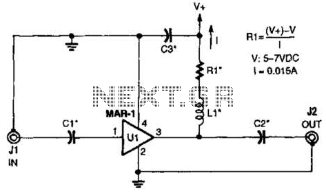
The low-cost Mini-Circuits MAR-X series of chips provides a significant advantage for RF builders, featuring inherent 50-ohm input and output impedances essential for RF systems. An MAR-1-based receiver/scanner preamplifier is illustrated. Capacitors Ci and C2 are chip capacitors, with...
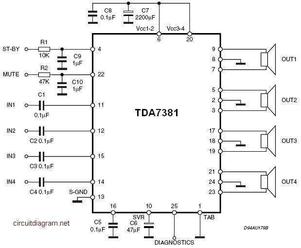
The TDA7381 is a Class AB audio power amplifier housed in a Flexiwatt25 package, specifically intended for car radio applications. This circuit can also be utilized for various other purposes. The fully complementary PNP/NPN output configuration enables a rail-to-rail...
The project involves the development of a miniature transmitter suitable for implantation in a rat's body, capable of transmitting 416-bit data samples at a rate of 400 samples per second. It is designed to have a detection range of...
Electronic Miss Manners infrared receiver and voice circuits The Electronic Miss Manners system integrates an infrared (IR) receiver with voice circuits to facilitate communication and interaction. The IR receiver is designed to detect signals emitted from a remote control or...
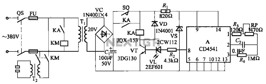
One Foot Spot Welder circuit. The circuit utilizes the IC CD4541 to provide precise delay characteristics, enabling the electrical time constant necessary for effective welding. This ensures consistent welding quality across identical weldments. For varying weldments, the electrical locator...