
Receiver/Scanner Preamp Circuit

The Mini-Circuits MAR-X series is specifically designed for RF applications, making it an excellent choice for integrating into preamplifier circuits. The inherent 50-ohm impedance facilitates optimal matching in RF systems, minimizing signal reflection and maximizing power transfer. The MAR-1-based preamplifier circuit comprises several key components that work together to amplify weak RF signals effectively.
In the schematic, Ci and C2 play a crucial role in coupling and decoupling signals at different frequency ranges. The choice of capacitance values is critical; for high-frequency applications (HF), a 0.01 µF capacitor is utilized, while VHF applications typically require a 0.001 µF capacitor. For frequencies above 100 MHz, a 100 pF capacitor is recommended, allowing for flexibility in tuning the circuit to specific frequency ranges and ensuring optimal performance.
C3, as a ceramic disc capacitor, provides additional filtering and stability in the circuit. Its value can also be selected based on the desired frequency characteristics, with options of 0.01 µF or 0.001 µF. This selection aids in maintaining the integrity of the RF signal while minimizing noise and distortion.
Inductor L1, characterized as an RF choke, is essential for blocking high-frequency noise while allowing the desired RF signals to pass through. The inductance value, ranging from 0.1 to 10 µH, should be chosen according to the specific frequency range of interest. This component is crucial for maintaining the stability and performance of the preamplifier, ensuring that the amplified output remains clean and free from unwanted interference.
Overall, the MAR-1-based receiver/scanner preamplifier circuit, utilizing the Mini-Circuits MAR-X series components, is an effective solution for RF signal amplification, providing flexibility in component selection to accommodate various frequency ranges and applications. The low-cost Mini-Circuits MAR-X series of chips offer the RF builder a real advantage, with their inherent 50- input and output impedances (needed for RF systems). An MAR-1-based receiver/scanner preamplifier is shown. Ci and C2 are chip capacitors. Use 0.01 for HF, 0.001 for VHF, and 100 pF for above 100 MHz, depending on the low-frequency limit that you desire.
C3 can be a ceramic disc of 0.01 or 0.001, depending on frequency range. LI is an RF choke that is suitable for the frequency range that you desire (0.1 to 10uH).
Related Circuits
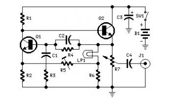
Set R5 to read 1V RMS on an audio millivoltmeter connected to the output with R7 rotated fully clockwise, or to view a sine wave of 2.828V peak-to-peak amplitude on the oscilloscope. An audio amplifier is an electronic device...

This circuit is designed as a countdown timer utilizing a countdown calculation. It employs the 555 integrated circuit (IC) as the primary control element. The 555 IC functions as a counter and a transistor switch to activate a relay...
This is a pressure sensor signal conditioning circuit. It is a simple and inexpensive circuit due to its small geometry and the use of a straightforward pressure sensor. The pressure sensor signal conditioning circuit is designed to convert the raw...
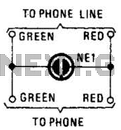
A neon lamp can easily be added to the phone line to act as a ring indicator. It is perfect for times when you cannot hear the phone. The integration of a neon lamp as a ring indicator in a...
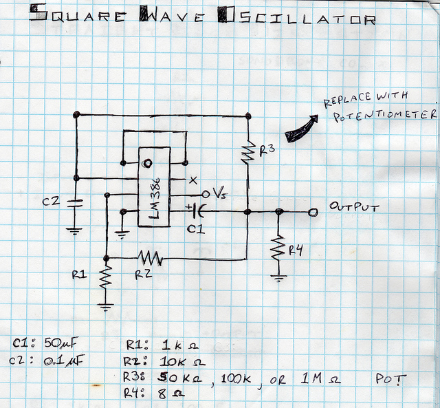
This is a square wave oscillator (digital, similar to 8-bit music). It is based on the LM386 amplifier integrated circuit, which is also the foundation for the mini guitar amplifier. The design includes a simple power switch connected to...
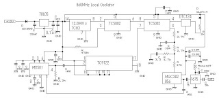
This 860 MHz Phase Locked Loop (PLL) oscillator circuit is designed for a 1200 MHz transverter's local oscillator with 435 MHz rigs. The oscillator utilizes Toshiba PLL synthesizer integrated circuits (ICs). The TC9122P serves as a preset counter for...