
Car Parking Sensor schematic

This parking assistance circuit is designed to enhance safety by providing visual alerts to the driver as they reverse their vehicle towards a garage wall. The primary components include infrared LEDs for transmission and a photo diode for reception, which work together to measure the distance to the wall. The system operates on the principle of reflected infrared light; as the vehicle approaches the wall, the intensity of the reflected light changes, triggering the corresponding LEDs to illuminate based on the preset distance thresholds.
The use of an NE555 timer (IC1) allows for precise timing control and signal processing, while the LM324 operational amplifier (IC2) can be used to amplify the signals received from the photo diode, ensuring that even minor changes in distance are detected. The LM7812 voltage regulator (IC3) ensures that the circuit operates at a stable voltage, which is crucial for maintaining consistent performance.
The choice of component values is critical for the desired sensitivity and response time of the circuit. Resistors R1 through R14 provide the necessary biasing and current limiting for the LEDs and the operational amplifier, while the capacitors help filter noise and stabilize the power supply. The infrared photo diode (D2) must be carefully selected to ensure it has an appropriate optical filter to minimize interference from ambient sunlight, thus enhancing the accuracy of distance measurement.
For practical implementation, it is recommended to assemble the circuit in a compact enclosure to protect the components and allow for easy installation in the vehicle. The signaling LEDs should be mounted in a position that is easily visible to the driver, ensuring that alerts can be quickly recognized during parking maneuvers. Proper calibration of the distance sensors is also essential, with adjustments made to ensure that the LED indicators provide accurate feedback as the vehicle approaches the wall.This circuit can be used for an assist in parking the car near the garage wall backing up Pls. LED D7 illuminates Pls bumper-wall distance is about 20 cm. , D7 + D6 illuminate at about 10 cm. and D7 + D6 + D5 at about 6 cm. In this manner you are alerted Pls approaching too close to the wall. All distances mentioned before can vary, depending on in fra-red transmitting and receiving LEDs used and are mostly affected by the color of the reflecting surface. Black surfaces lower greatly the device sensitivity. Obviously, you can use this circuit in other applications like liquids level detection, proximity devices etc.
The infra-red Photo Diode D2, should be of the type incorporating an optical sunlight filter: these components appear in black plastic cases. Some of them resemble TO92 transistors: in this case, please note that the sensitive surface is the curved, not the flat one.
It is wiser to place all the circuitry near the infra-red LEDs in a small box. The 3 signaling LEDs can be placed far from the main box at an height making them well visible by the car driver. The best setup is obtained bringing D2 nearer to D1 (without a reflecting object) until D5 illuminates; then moving it a bit until D5 is clearly off.
Usually D1-D2 optimum distance lies in the range 1. 5-3 cm. R1 : 10K R2, R5, R6, R9 : 1K R3 : 33R R4, R11 : 1M R7 : 4K7 R8 : 1K5 R10, R12-R14 : 1K C1, C4 : 1 µF/63V C2 : 47pF C3, C5 : 100 µF D1 : Infra-red LED D2 : Infra-red Photo Diode (see Notes) D3, D4 : 1N4148 D5-7 : LEDs (Any color and size) IC1 : NE555 IC2 : LM324 IC3 : LM7812 🔗 External reference
Related Circuits
This DIY magnetic field sensor circuit is straightforward and capable of detecting both fixed magnetic fields and those that vary at audio frequencies. The device is not designed for precise measurement of magnetic field strength. A small and relatively...
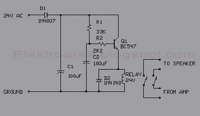
This circuit was designed for an audio amplifier project to control the speaker output relay. The primary function of this circuit is to manage the relay that activates the speaker output in the audio amplifier. The circuit introduces a...
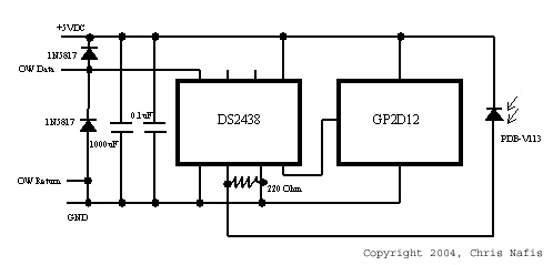
A sensor is being developed to measure snowfall. If this sensor can be produced at a low cost, the potential of the Internet can be harnessed to gather extensive data across large areas. Current popular weather data collection platforms,...
Dark Activated Switch or Porch Light Switch. This circuit activates a relay when the light level drops below a preset threshold. The light sensitivity can be adjusted using variable resistor VR1, and the relay contacts can control an external...
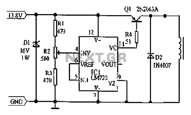
Cars are equipped with a circuit that includes an LM723 regulator, which can serve as a replacement for traditional automobile generator systems that utilize electromechanical charging regulators. This circuit offers superior performance compared to conventional systems. It ensures that...
Ions are defined as electrically charged atoms. Positively charged ions have a deficiency of electrons, and negatively charged ions have a surplus of electrons. An ion can also be classified as an atom or molecule with an electrostatic charge....