
simple delay speaker circuit schematic

The circuit employs a relay to manage speaker connection and disconnection based on the amplifier's power state. The delay mechanism is crucial for preventing speaker damage and undesirable audio artifacts during power transitions. The charging of C1 and C2 is integral to the timing aspect; C1 provides initial power stabilization while C2's charging rate, governed by R1, dictates the delay duration. The choice of components, particularly the values of C2 and R1, allows for customization of the delay period to suit specific application needs.
Transistors Q1 and Q2 serve as the control elements within the circuit. Q1 operates as a switch that is turned on when the voltage across C2 reaches a certain threshold, allowing current to flow and energizing the relay. Q2 amplifies the control signal from Q1, ensuring that the relay is adequately driven to its on state, which is essential for reliable operation. The relay itself must be rated appropriately for the speaker load and the amplifier's output characteristics to ensure safe and effective operation.
In summary, this circuit effectively integrates timing and control elements to enhance the performance of audio amplifiers, providing a practical solution to common issues associated with speaker connection and disconnection during power transitions.This is scircuit which I built to one of audio amplifier projects to control the speaker output relay. The purpose of this circuit is to control the relay which turns on the speaker output relay in the audio amplifier.
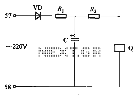
The idea of the circuit is wait around 5 seconds ofter the power up until the spakers are switched to the amplfier output to avoid annoying "thump" sound from the speakers. Another feeature of this circuit is that is disconnects the speaker immdiatly when the power in the amplifier is cut off, so avoinding sometimes nasty sounds when you turn the equipments off. Then power is applied to the power input of the circuit, the positive phase of AC voltage charges C1.
Then C2 starts to charge slowly through R1. When the voltage in C2 rises, the emitter output voltage of Q1 rises tigether with voltage on C2. When the output voltage of Q2 is high enough (typically around 16. 20V) the relay goes to on state and the relay witches connect the speakers to the amplifier output. It takes typically around 5 seconds after power up until the relay starts to condict (at absolute time depends on the size of C2, relay voltage and circuit input voltage). 🔗 External reference
Related Circuits
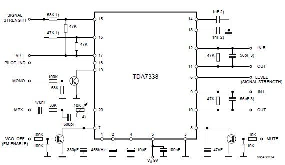
The pilot detector output is configured as an open collector output, necessitating the use of an external pull-up resistor. To set the decoder to "MONO," Pin 19 must be clamped to a voltage lower than 0.8V. The open collector output...
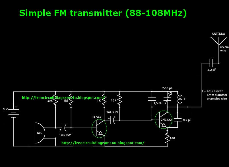
This is a simple transmitter circuit diagram that offers decent coverage. The circuit can operate with a power supply of 9-12V. To tune this circuit... This simple transmitter circuit is designed to provide reliable performance within the specified voltage range....
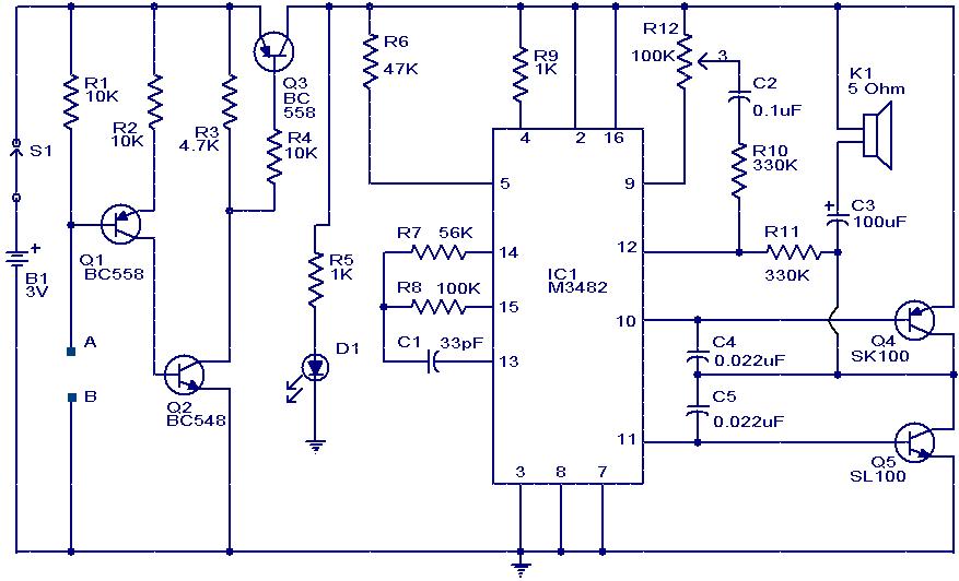
This is a hobby circuit designed as a water or liquid sensor. Its primary function is to activate an alarm when water or liquid is detected at its probes. The water sensor circuit typically consists of a few essential components,...
A very simple DIY crystal oscillator circuit that uses a quartz crystal for frequency stability and a suitable RF transistor. It employs a second or third harmonic crystal for operation. This DIY crystal oscillator circuit is designed to generate stable...
Undervoltage release operates over an extended period. When the power supply voltage drops within the operating voltage range, it triggers the release mechanism, resulting in the rotation of the tripping axle and the disconnection of the circuit breaker. There...
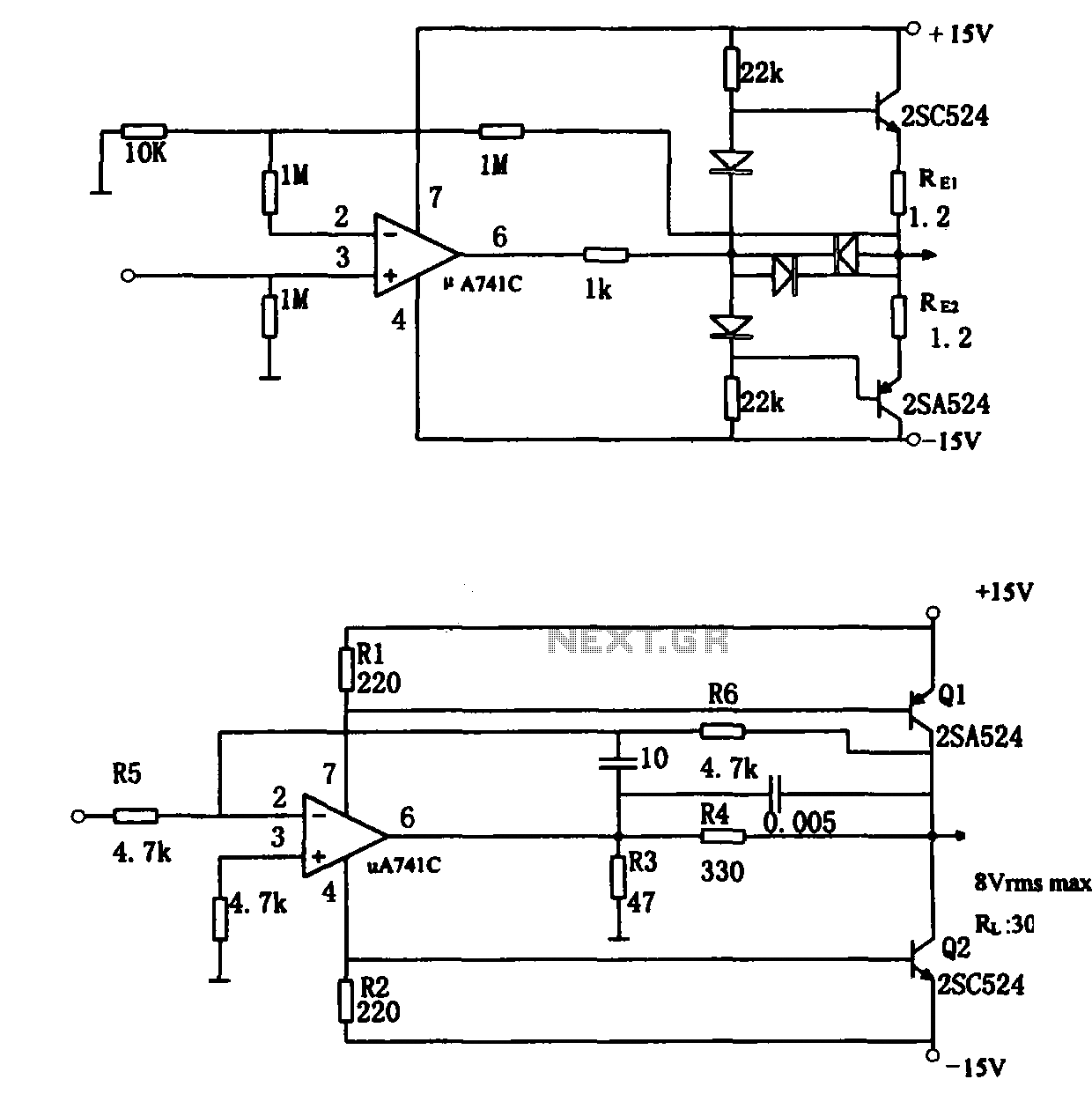
The direct coupling audio power amplifier utilizes an integrated operational amplifier. There are typically two practical configurations. The first configuration, depicted in (a), features a circuit structure that includes the output of the operational amplifier and a complementary symmetry...