
Car subwoofer filter

The subwoofer filter circuit is essential for enhancing low-frequency audio performance in automotive sound systems. The TL072 op-amp is selected for its low noise and high-speed characteristics, making it suitable for audio applications. The buffer configuration of IC1A ensures that the audio signal maintains its integrity and is not loaded down by subsequent stages of the circuit.
The DPDT switch (S1) allows the user to select between two phase options. This feature is crucial in multi-speaker setups, where phase alignment can significantly affect sound quality and coherence. A phase shift may be necessary depending on the placement of the subwoofer relative to other speakers, and the ability to toggle this setting enhances the flexibility of the system.
Potentiometer R7 provides a convenient means to adjust the subwoofer output level, allowing for fine-tuning to match the overall sound system's characteristics. The low pass filter configuration created by IC1B is pivotal in ensuring that only the desired low-frequency signals pass through to the subwoofer, while higher frequencies are attenuated. The dual gang potentiometer R13 allows for precise control over the cutoff frequency, enabling the user to tailor the filter's response to the specific acoustic environment and personal preferences.
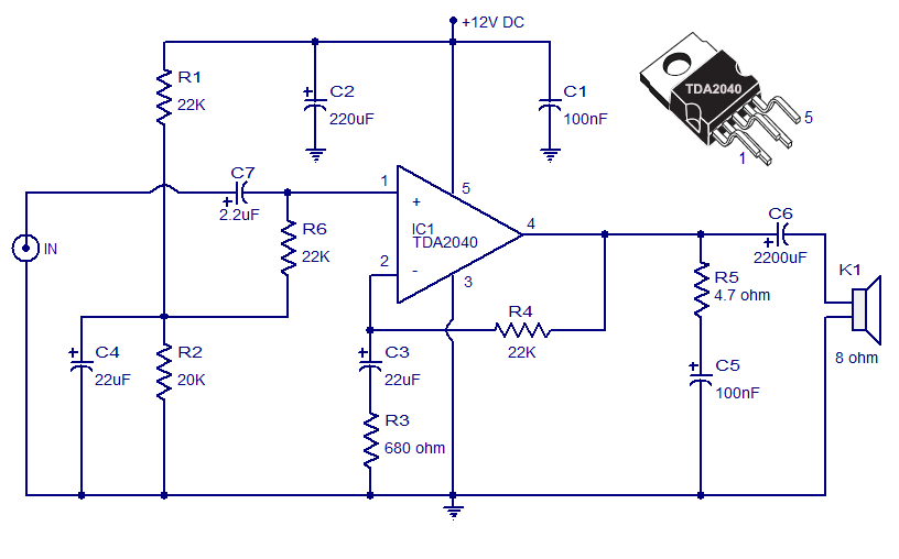
Overall, this circuit design effectively integrates phase control and frequency adjustment features, making it a versatile solution for automotive audio systems that require enhanced sub-bass performance.Here is the circuit diagram of a simple subwoofer filter that can be operated from a 12V DC supply. Such a circuit is very useful in automobile subwoofer applications. The circuit is nothing but a low pass filter whose pass frequency can be adjusted between 60 to 160 Hz. The circuit is designed around the TL072 dual BIFET opamp IC. Out of the two opamps inside the chip, IC1A is wired as a buffer. The left and right audio inputs after mixing is fed to the input of the IC1A using the DPDT switch S1. Switch S1 is the phase control switch which can be used to make the subwoofer in phase with other speakers.
When S1 is in position 2, 180 degree phase shift will be induced. POT R7 can be used for controlling the level. IC1B forms the low pass filter whose pass frequency can be controlled by adjusting the dual gang POT R13. 🔗 External reference
Related Circuits
Battery Indicator Circuit for the Caravan. This i-TRIXX circuit can prevent a lot of trouble for those who go on holiday in a caravan. It would be a significant damper on your holiday spirit when you are unprepared. The Battery...

Due to the amplifier's frequency characteristics and the impact of parasitic capacitance, designing an active filter that operates effectively at hundreds of kilohertz is quite challenging. Additionally, since the circuit consists of a low-pass filter with a large coil...
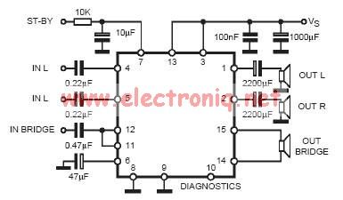
In practical applications, a series resistance must always be included. This component serves the dual purpose of limiting the current at pin 7 and smoothing the ON/OFF transitions during standby. In electronic circuits, particularly those involving integrated circuits (ICs) or...
The Car Stereo Amplifier Circuit featuring the TDA2040 is presented here. The TDA2040 is a monolithic integrated audio amplifier that operates in Class AB mode. This integrated circuit includes built-in short circuit protection and thermal management features, allowing it...
The core of a typical RMS calibrated AC voltmeter consists of a rectifier and averaging filter. To create a precision full-wave rectifier, the averaging function can be removed by eliminating capacitor C2, while deleting capacitor C1 will enable the...
The acoustic spectrum extends from a very low frequency of 20 Hz to a high frequency of 20,000 Hz. At lower frequencies, the sense of direction diminishes. This observation leads to the recommendation of using speakers that handle very...