
Battery Indicator Circuit For The Caravan

The Battery Indicator Circuit is designed to monitor the voltage levels of a caravan’s battery, providing real-time feedback on the battery's state of charge. This circuit is essential for ensuring that the battery remains within optimal operating conditions, thus preventing situations where the battery is overly discharged, which can lead to failure or reduced lifespan.
The circuit typically employs a microcontroller or a simple voltage divider to measure the battery voltage. An LED indicator is commonly used to signal the battery's status. For example, a green LED might indicate that the battery is fully charged, a yellow LED could signify a moderate charge level, and a red LED would alert the user to a low charge condition.
To implement this circuit, the following components are generally required: a voltage regulator to ensure stable operation, resistors to create the voltage divider, LEDs for visual indicators, and a microcontroller for processing the voltage readings. The circuit can be powered directly from the caravan's battery, ensuring that it operates even when the vehicle is not in use.
In addition to visual indicators, the circuit can be enhanced with audible alarms that activate when the battery voltage drops below a certain threshold. This feature provides an additional layer of safety, alerting the user to take action before the battery becomes critically low.
Overall, the Battery Indicator Circuit serves as a vital tool for caravan owners, enhancing the reliability of the electrical system and contributing to a more enjoyable holiday experience by preventing unexpected battery failures.Battery Indicator Circuit For The Caravan Circuit This i-TRIXX circuit can prevent a whole lot of trouble for those of you who go on holiday in a caravan. It would be a significant damper on your holiday spirit when you are read.. 🔗 External reference
Related Circuits
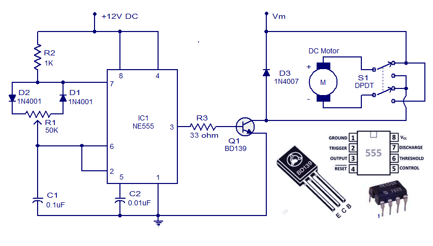
This weblog discusses electronic circuit schematics, PCB design, DIY kits, and electronic project diagrams. A simple DC motor controller circuit utilizing the NE555 timer is presented. Several DC motor speed control circuits are explored, with this being the first...
The circuits on this page are for an Infrared Proximity Detector using the Vishay Electronics TSOP4830, which is an IR Receiver Module designed for remote control systems. The TSOP4830 functions as a sensitive infrared detector that operates without requiring...
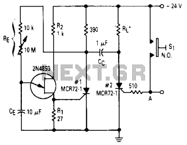
After one cycle of operation, SCR1 will be activated, resulting in a low voltage being applied to the UJT emitter circuit, which interrupts the tuning function. When pushbutton SI is pressed, or a positive pulse is applied at point...
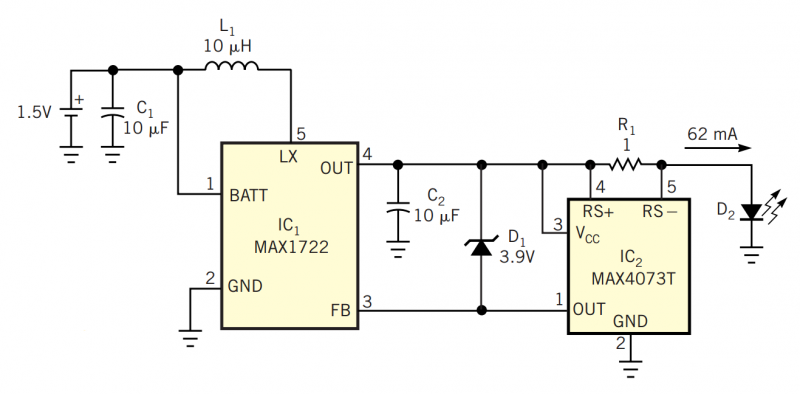
Although white LEDs are common in a variety of lighting applications, their 3 to 4V forward-voltage drop makes low-voltage applications challenging. Charge pumps and other ICs are available for driving white LEDs, but they generally don't work with the...

This circuit conducts a rapid battery test without requiring an external power supply or costly moving-coil voltmeters. It offers two testing ranges: when switch SW1 is configured as indicated in the circuit diagram, it can evaluate batteries ranging from...
This compact single-chip circuit is designed for measuring the level of electrically conductive fluids or liquids. It functions as a voltage level sensor and employs an AC bias supply to prevent electrolysis of the probes, thereby enhancing their lifespan....